


4
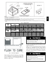
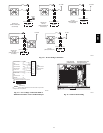
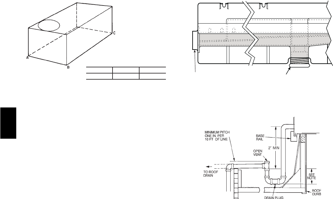
MAXIMUM ALLOWABLE
DIFFERENCE (in.)
A-B B-C A-C
0.5 1.0 1.0
C06110
Fig. 3 --- Unit Leveling Tolerances
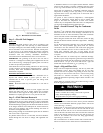
Be sure that unit is installed such that snow will not block the
combustion intake or flue outlet.
Unit may be installed directly on wood flooring or on Class A, B,
or C roof-covering material when roof curb is used.
Although unit is weatherproof, guard against water from higher
level runoff and overhangs.
Locate mechanical draft system flue assembly at least 48 in. from
an adjacent building or combustible material. When unit is
located adjacent to public walkways, flue assembly must be at
least 7 ft above grade.
NOTE: When unit is equipped with an accessory flue discharge
deflector, a llowable clearance is 18 inches.
Flue gas can deteriorate building materials. Orient unit such that
flue gas will not affect building materials.
Adequate combustion-air space must be provided for proper
operation of this equipment. Be sure that installation complies
with all local codes and Section 5.3, Air for Combustion and
Ventilation, NFGC (National Fuel Gas Code), ANSI (American
National Standards Institute) Z223.1-1984 and addendum
Z223.1a-1987. In Canada, installation must be in accordance with
the CAN1.B149.1 and CAN1.B149.2 installation codes for gas
burning appliances.
Flue vent discharge must have a minimum horizontal clearance of
4 ft from electric and gas meters, gas regulators, and gas relief
equipment.
After unit is in position, remove shipping materials and rigging
skids.
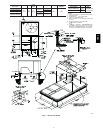
Step 5 —Install Flue Hood
Flue hood is shipped screwed to the burner compartment access
panel. Remove from shipping location and, using screws
provided, install flue hood in location shown in Fig. 8 and 9.
For units being installed in California Air Quality Management
Districts which require NOx emissions of 40 nanograms/joule or
less, a low NOx unit must be installed.
NOTE: Low NOx units are available for 2 to 5 ton units.
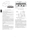
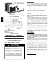
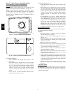
DRAIN PLUG
CONDENSATE PAN (SIDE VIEW)
HORIZONTAL
DRAIN OUTLET
NOTE: Drain plug is shown in factory-installed position.
C06003
Fig. 4 --- Condensate Drain Pan
NOTE: Trap should be deep enough to offset maximum unit static
difference. A 4-in. trap is recommended.
C06004
Fig. 5 --- Condensate Drain Piping Details
Step 6 —Install Gas Piping
Unit is equipped for use with type of gas shown on nameplate.
Refer to local building codes, or in the absence of local codes,
to ANSI Z223.1-1984 and addendum Z223.1A-1987 entitled
National Fuel Gas Code. In Canada, installation must be in
accordance with the CAN1.B149.1 and CAN1.B149.2
installation codes for gas burning appliances.
For natural gas applications, gas pressure at unit gas connection
must not be less than 4 in. wg or greater than 13 in. wg while the
unit is operating. On 581B036 --072 and 581C036--060 high-heat
units, the gas pressure at unit gas connection must not be less than
5 in. wg or greater than 13 in. wg while the unit is operating. For
propane applications, the gas pressure must not be less than 5 in.
wg or greater than 13 in. wg at the unit connection.
Size gas supply piping for 0.5 in. wg maximum pressure drop.
Do not use supply pipe smaller than unit gas connection.
581B,C