


24
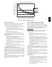
CONTROL
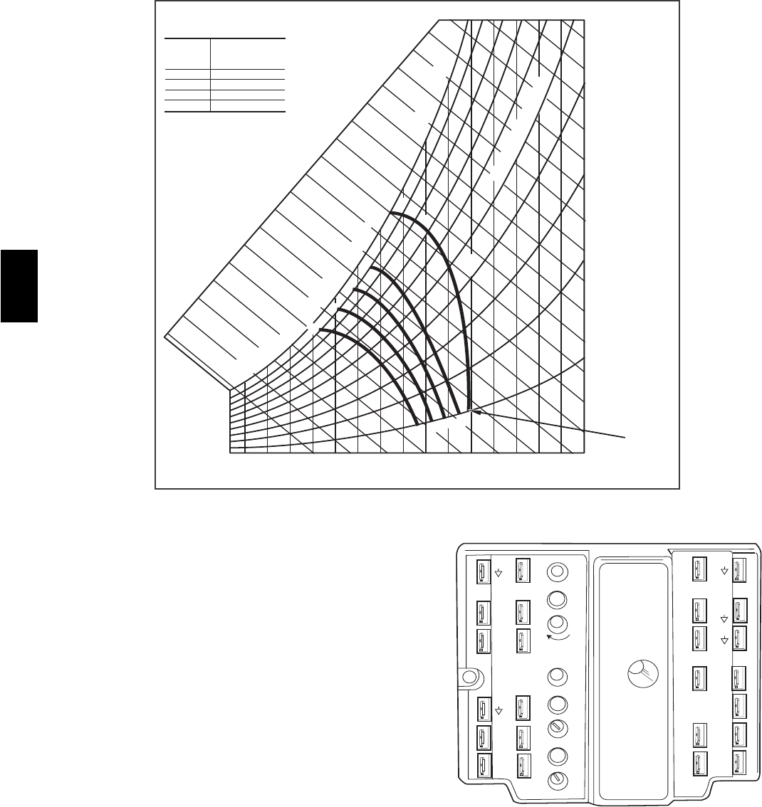
CURVE
A
B
C
D
CONTROL POINT
APPROX.
deg. F (deg. C)
AT 50% RH
73 (23)
70 (21)
67 (19)
63 (17)
1
2
1
4
1
6
1
8
2
0
2
2
2
4
26
28
30
32
3
4
3
6
3
8
40
42
4
4
46
9
0
1
0
0
80
70
6
0
50
4
0
30
20
1
0
ENTHALPY BTU PER POUND DRY AIR
85
(29)
90
(32)
95
(35)
100
(38)
105
(41)
110
(43)
35
(2)
35
(2)
40
(4)
40
(4)
105
(41)
110
(43)
45
(7)
45
(7)
50
(10)
50
(10)
55
(13)
55
(13)
60
(16)
60
(16)
65
(18)
65
(18)
70
(21)
70
(21)
75
(24)
75
(24)
80
(27)
80
(27)
85
(29)
90
(32)
95
(35)
100
(38)
A
A
B
B
C
C
D
D
RELATIVE HUMIDITY (%)
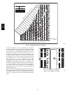
HIGH LIMIT
CURVE
APPROXIMATE DRY BULB TEMPERATURE--degrees F (degrees C)
C06037
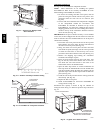
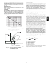
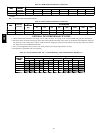
Fig. 38 --- Enthalpy Changeover Set Points
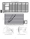
The same equation can be used to determine the occupied or
maximum ventilation rate to the building. For example, an output
of 3.6 volts to the actuator provides a base ventilation rate of 5%
and an output of 6.7 volts provides the maximum ventilation rate
of 20% (or base plus 15 cfm per person). Use Fig. 37 to
determine the maximum setting of the CO
2
sensor. For example,
a 1100 ppm set point relates to a 15 cfm per person design. Use
the 1100 ppm curve on Fig. 40 to find the point when the CO
2
sensor output will be 6.7 volts. Line up the point on the graph
with the l eft side of t he chart to determine that the range
configuration for the CO
2
sensor should be 1800 ppm. The
EconoMi$er IV controller will output the 6.7 volts from the CO
2
sensor to the actuator when the CO
2
concentration in the space is
at 1100 ppm. The DCV set point may be left at 2 volts since the
CO
2
sensor voltage will be ignored by the EconoMi$er IV
controller until it rises above the 3.6 volt setting of the minimum
position potentiometer.
Once the fully occupied damper position has been determined, set
the maximum damper demand control ventilation potentiometer
to this position. Do not set to the maximum position as this can
result in over-ventilation to the space and potential high-humidity
levels.
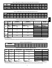
TR1
24 Vac
COM
TR
24
Vac
HOT
12
3
4
5
EF
EF1
+
_
P1
T1
P
T
N
EXH
2V 10V
EXH
Set
Set
2V 10V
2V 10V
DCV
DCV
Free
Cool
B
C
A
D
SO+
SR+
SR
SO
AQ1
AQ
DCV
Min
Pos
Open
Max
N1
C06038
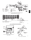
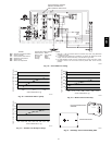
Fig. 39 --- EconoMi$er IV Control
581B,C