


43
Heating
1. Purgegas supply line of air by opening union ahead of the
gas valve. If gas odor is detected, tighten union and wait 5
minutes before proceeding.
2. Turn on electrical supply and manual gas valve.
3. Set system switch selector at HEAT position and fan
switch at AUTO or ON position. Set heating temperature
lever above room temperature.
4. The induced-draft motor will start.
5. After a call for heating, the main burners should light
within 5 seconds. If the burner does not light, then there is
a 22-second delay before another 5-second try. If the
burner still does not light, the time delay is repeated. If the
burner does not light within 15 minutes, there is a lockout.
To reset the control, break the 24 v power to W1.
6. The evaporator-fan motor will turn on 45 seconds after
burner ignition.
7. The evaporator-fan motor will turn off in 45 seconds after
the thermostat temperature is satisfied.
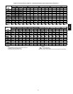
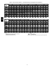
8. Adjust airflow to obtain a temperature rise within the
range specified on the unit nameplate.
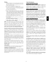
NOTE: The default value for the evaporator-fan motor on/off
delay is 45 seconds. The Integrated Gas Unit Controller (IGC)
modifies this value when abnormal limit switch cycles occur.
Based upon unit operating conditions, the on delay can be
reduced to 0 seconds and the off delay can be extended to 180
seconds. When one flash of the LED (light-emitting diode) is
observed, the evaporator-fan on/off delay has been modified.
If the limit switch trips at the s tart of the heating cycle during the
evaporator on delay, the time period of the on delay for the next
cycle will be 5 seconds less than the time at which the switch
tripped. (Example: If the limit switch trips at 30 seconds, the
evaporator-fan on delay for the next cycle will occur at 25
seconds.) To prevent short-cycling, a 5-second reduction will
only occur if a minimum of 10 minutes has elapsed since the last
call for heating.
The evaporator-fan off delay can also be modified. Once the call
for heating has ended, there is a 10-minute period during which
the modification can occur. If the limit switch trips during this
period, the evaporator-fan off delay will increase by 15 seconds.
A maximum of 9 trips can occur, extending the evaporator-fan off
delay to 180 seconds.
To restore the original default value, reset the power to the unit.
To Shut Off Unit —Set system selector switch at off position.
Resetting heating selector lever below room temperature will
temporarily shut unit off until space temperature falls below
thermostat setting.
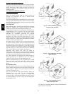
Safety Relief
A soft solder joint at the suction line fitting provides pressure
relief under abnormal temperature and pressure conditions.
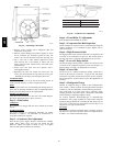
Ventilation (Continuous Fan)
Set fan and system selector switches at ON and OFF positions,
respectively. Evaporator fan operates continuously to provide
constant air circulation. When the evaporator--fan selector switch
is turned to the OFF position, there is a 30--second delay before
the fan turns off.
Operating Sequence
Cooling -- Units Without Economizer
When thermostat calls for cooling, terminals G and Y1 are
energized. The indoor-fan contactor (IFC), reversing valve
solenoid (RVS) and compressor contactor are energized and
indoor-fan motor, compressor, and outdoor fan starts. The
outdoor fan motor runs continuously while unit is cooling.
Heating -- Units Without
Economizer
When the thermostat calls for heating, terminal W1 is ener gized.
To prevent thermostat short--cycling, the unit is locked into the
Heating mode for at least 1 minute when W1 is energized. The
induced--draft motor is energized and the burner ignition
sequence begins. The indoor (evaporator) fan motor (IFM) is
energized 45 seconds after a flame is ignited. On units equipped
for two stages of heat, when additional heat is needed, W2 is
energized and the high--fire solenoid on the main gas valve
(MGV) is energized. When the thermostat is satisfied and W1 is
deenergized, the IFM stops after a 45 --second time--off delay.
Cooling -- Units With Economi$er
IV
When free cooling is not available, the compressors will be
controlled by the zone thermostat. When freecooling is available,
the outdoor-air damper is modulated by the EconoMi$er IV
control to provide a 50_ to 55_F supply-air temperature into the
zone. As the supply-air temperature fluctuates above 55_ or
below 50_F, the dampers will be modulated (open or close) to
bring the supply-air temperature back within the set point limits.
Integrated EconoMi$er IV operation on single-stage units
requires a 2-stage thermostat (Y1 and Y2).
For EconoMi$er IV operation, there must be a thermostat call for
the fan (G). This will move the damper to its minimum position
during the occupied mode.
If the increase in cooling capacity causes the supply--air
temperature to drop below 45_F, then the outdoor-- air damper
position will be fully closed. If the supply--air temperature
continues to fall, the outdoor-- air damper will close. Control
returns to normal once the supply-- air temperature rises above
48_F.
If optional power exhaust is installed, as the outdoor--air damper
opens and closes, the power exhaust fans will be energized and
deenergized.
If field--installed accessory CO
2
sensors are connected to the
EconoMi$er IV control, a demand controlled ventilation strategy
will begin to operate. As the CO
2
level in the zone increases
above the CO
2
set point, the minimum position of the damper
will be increased proportionally. As the CO
2
level decreases
because of the increase in fresh air, the outdoor-- air damper will
be proportionally closed. Damper position will follow the higher
demand condition from DCV mode or free cooling mode.
Damper movement from full closed to full open (or vice versa)
will take between 1--1/2 and 2--1/2 minutes.
If free cooling can be used as determined from the appropriate
changeover command (switch, dry bulb, enthalpy curve,
differential dry bulb, or differential enthalpy), a call for cooling
(Y1 closes at the thermostat) will cause the control to modulate
the dampers open to maintain the supply air temperature set point
at 50_ to 55_F.
As the supply air temperature drops below the set point range of
50_ to 55_F, the control will modulate the outdoor--air dampers
closed to maintain the proper supply--air temperature.
581B,C