


22
SUPPLY AIR
TEMPERATURE
SENSOR
MOUNTING
LOCATION
SUPPLY AIR
TEMPERATURE
SENSOR
C06033
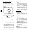
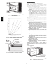
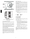
Fig. 34 --- Supply Air Sensor Location
C06034
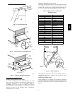
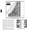
Fig. 35 --- EconoMi$er IV Controller Potentiometer
and LED Locations
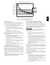
Indoor Air Quality (IAQ) Sensor Input
The IAQ input can be used for demand control ventilation control
based on the level of CO
2
measured in the space or return air
duct.
Mount the accessory IAQ sensor according to manufacturer
specifications. The IAQ sensor is wired to the AQ and AQ1
terminals of the controller. Adjust the DCV potentiometers to
correspond to the DCV voltage output of the indoor air quality
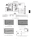
sensor at the user-determined set point. (See Fig. 40.)
If a separate field-supplied transformer is used to power the IAQ
sensor, the sensor must not be grounded or the EconoMi$er IV
control board will be damaged.
Exhaust Set Point Adjustment
The exhaust set point will determine when the exhaust fan runs
based on damper position (if accessory power exhaust is
installed). The set point is modified with the Exhaust Fan Set
Point (EXH SET) potentiometer. (See Fig. 35.) The set point
represents the damper position above which the exhaust fans will
be turned on. When there is a call for exhaust, the EconoMi$er IV
controller provides a 45 15 second delay before exhaust fan
activation to allow the dampers to open. This delay allows the
damper to reach the appropriate position to avoid unnecessary fan
overload.
Minimum Position Control
There is a minimum damper position potentiometer on the
EconoMi$er IV controller. (See Fig. 35.) The minimum damper
position maintains the minimum airflow into the building during
the occupied period.
When using demand ventilation, the minimum damper position
represents the minimum ventilation position for VOC (volatile
organic compound) ventilation requirements. The maximum
demand ventilation position is used for fully occupied ventilation.
When demand ventilation control is not being used, the minimum
position potentiometer should be used to set the occupied
ventilation position. The maximum demand ventilation position
should be turned fully clockwise.
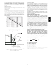
Adjust the minimum position potentiometer to allow the
minimum amount of outdoor air, as required by local codes, to
enter the building. Make minimum position a djustments with at
least 10_F temperature difference between the outdoor and
return-air temperatures.
To determine the minimum position setting, perform the
following procedure:
1. Calculate the appropriate mixed air temperature using the
following formula:
(
T
OA
)
+
(
T
R
x
RA
)
T
(
T
Ox
100
)
+
(
T
R
x
100
)
=T
M
T
O
= Outdoor-Air Temperature
OA = Perc ent of O ut door Ai r
T
R
= R et ur n-Ai r Temper at ur e
RA = Percent of Return Air
T
M
= Mixed-Air Temperature
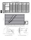
As an example, if local codes require 10% outdoor air during
occupied conditions, outdoor-air temperature is 60_F, and
return-air temperature is 75_F.
(60 x .10) + (75 x .90) = 73.5_F
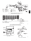
2. Disconnect the supply air sensor from terminals T and T1.
3. Ensure that the f actory-installed j umper is in place across
terminals P and P1. If remote damper positioning is being
used, make sure that the terminals are wired according to
Fig. 29 and that the minimum position potentiometer is
turned fully clockwise.
4. Connect 24 vac across terminals TR and TR1.
5. Carefully adjust the minimum position potentiometer
until the measured supply air temperature matches the
calculated value.
6. Reconnect the mixed air sensor to terminals T and T1.
Remote control of the EconoMi$er IV damper is desirable when
requiring additional temporary ventilation. If a
field-supplied remote potentiometer (Honeywell part number
S963B1128) is wired to the EconoMi$er IV controller, the
minimum position of the damper can be controlled from a remote
location.
581B,C