


46
C06046
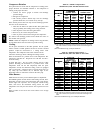
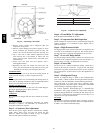
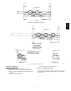
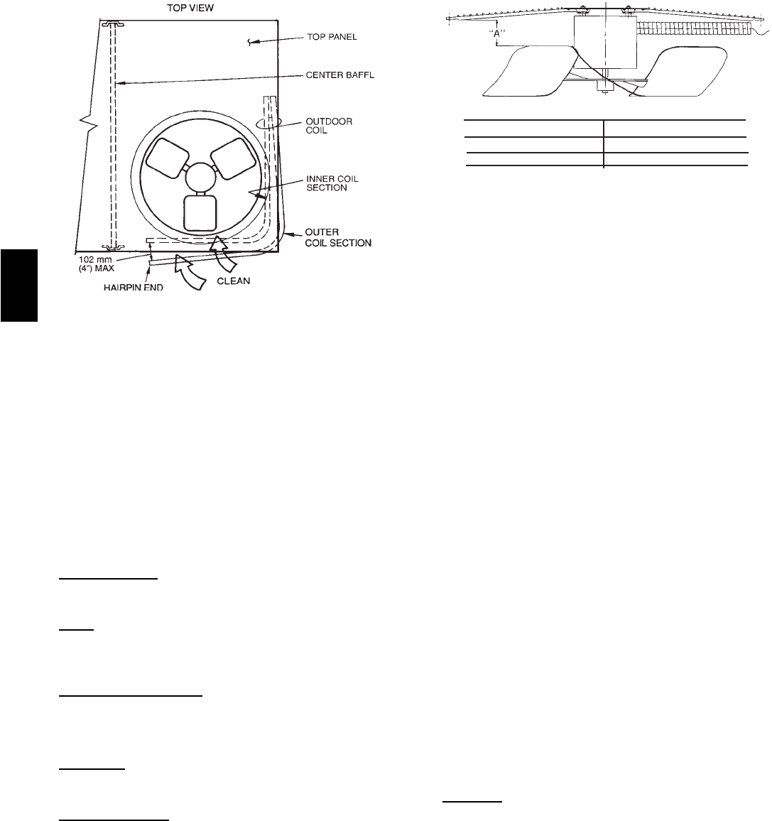
Fig. 49 --- Separating Coil Sections
4. Remove screws securing coil to compressor plate and
compressor access panel.
5. Remove fastener holding coil sections together at return
end of condenser coil. Carefully separate the outer coil
section 3 to 4 in. from the inner coil section. (See Fig. 49.)
6. Use a water hose or other suitable equipment to flush
down between the 2 coil sections to remove dirt and
debris. Clean the outer surfaces with a stiff brush in the
normal manner.
7. Secure inner and outer coil rows together with a
field-supplied fastener.
8. Reposition the outer coil section and remove the coil
corner post from between the top panel and center post.
Reinstall the coil corner post and replace all screws.
Condensate
Drain
Check and clean each year at the start of the cooling season. In
winter, keep the drain dry or protect it against freeze-up.
Filters
Clean or replace at the start of each heating and cooling season, or
more often i f operating conditions require it. Replacement filters
must be the same dimensions as the original filters.
Outdoor--Air Inlet Scr
eens
Clean the screens with steam or hot water and a mild detergent.
Do not use disposable filters in place of screens.
Step 2 —Lubrication
Compressor
The compressor is charged with the correct amount of oil at the
factory.
Fan Motor
Bearings
Fan motor bearings are permanently lubricated. No further
lubrication is required. No lubrication of condenser-fan or
evaporator-fan motors is required.
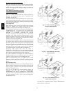
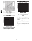
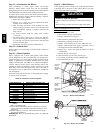
Step 3 —Condenser--Fan Adjustment
Shut off unit power supply. Remove condenser-fan assembly
(grille, motor, motor cover , and fan) and loosen fan hub
setscrews. Adjust fan height as shown in Fig. 50. Tighten
setscrews and replace condenser-fan assembly.
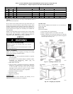
UNIT
FAN HEIGHT (in.) - A
024-060 and 072 (208/230 v)
072 (460 v)
2.75
3.50
C06138
Fig. 50 --- Condenser--Fan Adjustment
Step 4 —EconoMi$er IV Adjustment
Refer to Optional EconoMi$er IV section.
Step 5 —Evaporator Fan Belt Inspection
Check condition of evaporator belt or tension during heating and
cooling inspections or as conditions require. Replace belt or
adjust as necessary.
Step 6 —High Pressure Switch
The high-pressure switch contains a Schrader core depressor, and
is located on the compressor hot gas line. This switch opens at
428 psig and closes at 320 psig. No adjustments are necessary.
Step 7 —Loss--of--Charge Switch
The loss-of-charge switch contains a Schrader core depressor, and
is located on the compressor liquid line. This switch opens at 7
psig and closes at 22 psig. No adjustments are necessary.
Step 8 —Freeze--Stat
The freeze-stat is a bimetal temperature-sensing switch that is
located on the “hair-pin” end of the evaporator coil. The switch
protects the evaporator coil from freeze-up due to lack of airflow.
The switch opens at 30_F and closes at 45_F. No adjustments are
necessary.
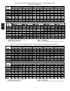
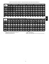
Step 9 —Refrigerant Charge
Amount of refrigerant charge is listed on unit nameplate (also
refer to Table 1). Refer to HVAC Servicing Procedures literature
available at your local distributor and the following procedures.
Unit panels must be in place when unit is operating during
charging procedure. Unit must operate a minimum of 10 minutes
before checking or adjusting refrigerant charge.
An accurate superheat, thermocouple-type or thermistor-type
thermometer, and a gauge manifold are required when using the
superheat charging method for evaluating the unit charge. Do not
usemercury or small dial-typethermometers because they are not
adequate for this type of measurement.
No
Charge
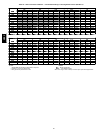
Use standard evacuating techniques. After evacuating system to
500 microns, weigh in the specified amount of refrigerant. (Refer
to Table 1 or 2 and unit information plate.)
581B,C