


23
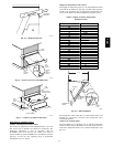
To control the minimum damper position remotely , remove the
factory-installed jumper on the P and P1 terminals o n the
EconoMi$er IV controller. Wire the field-supplied potentiometer
to the P and P1 terminals on the EconoMi$er IV controller. (See
Fig. 39.)
Damper Movement
Damper movement from full open to full closed (or vice versa)
takes 2
1
/
2
minutes.
Thermostats
The EconoMi$er IV control works with conventional thermostats
that have a Y1 (cool stage 1), Y2 (cool stage 2), W1 (heat stage
1), W2 (heat stage 2), and G (fan). The EconoMi$er IV control
does not support space temperature sensors. Connections are
made at the thermostat terminal connection board located in the
main control box.
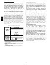
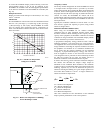
LED ON
LED ON
LED ON
LED ON
LED OFF
19
18
LED OFF
LED OFF
LED OFF
17
16
15
14
13
12
11
10
9
40
45
50
55
60
65
70
75
80
85
90
95
100
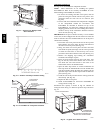
DEGREES FAHRENHEIT
mA
D
C
B
A
C06035
Fig. 36 --- Outside Air Te mperature
Changeover Set Points
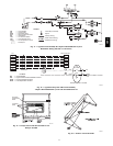
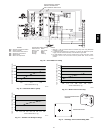
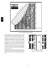
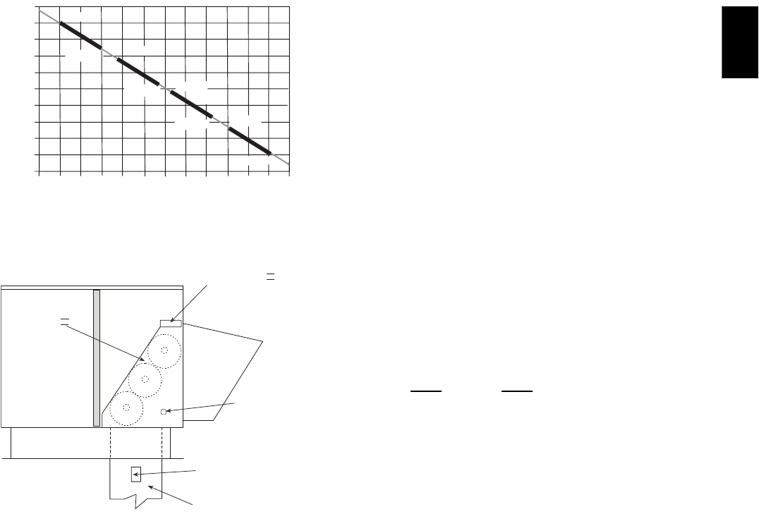
ECONOMI$ER IV
ECONOMI$ER IV
CONTROLLER
GROMMET
RETURNAIR TEMPERATURE
SENSOR
RETURN DUCT
(FIELD-PROVIDED)
C06036
Fig. 37 --- Return Air Temperatur e or Enthalpy
Sensor Mounting Location
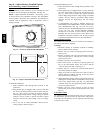
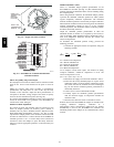
Occupancy Control
The factory default configuration for the EconoMi$er IV control
is occupied mode. Occupied mode is provided by the black
jumper from terminal TR to terminal N. When unoccupied mode
is desired, install a field-supplied timeclock function in place of
the jumper between TR and N. (See Fig. 29.) When the timeclock
contacts are closed, the EconoMi$er IV control will be in
occupied mode. When the timeclock contacts are open (removing
the 24-v signal from terminal N), the EconoMi$er IV will be in
unoccupied mode.
Typically the maximum ventilation rate will be a bout 5 to 10%
more than the typical cfm required per person, using normal
outside air design criteria.
Demand Controlled Ventilation (DCV)
When using the EconoMi$er IV for demand controlled
ventilation, there are some equipment selection criteria which
should be considered. When selecting the heat capacity and cool
capacity of the equipment, the maximum ventilation rate must be
evaluated for design conditions. The maximum damper position
must be calculated to provide the desired fresh air.
A proportional anticipatory strategy should be taken with the
following conditions: a zone with a large area, varied occupancy,
and equipment that cannot exceed the required ventilation rate at
design conditions. Exceeding t he required ventilation r ate means
the equipment can condition air at a maximum ventilation rate
that is greater than the required ventilation rate for maximum
occupancy. A proportional-anticipatory strategy will cause the
fresh air supplied to increase as the room CO
2
level increases
even though the CO
2
set point has not been reached. By the time
the CO
2
level r eaches the set point, the damper will be at
maximum ventilation and should maintain the set point.
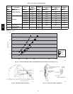
In order to have theCO
2
sensor control theeconomizerdamper in
this manner, first determine the damper voltage output for
minimum or base ventilation. Base ventilation is the ventilation
required to remove contaminants during unoccupied periods. The
following equation may be used to determine the percent of
outside-air entering the building for a given damper position. For
best results there should be at least a 10 degree difference in
outside and return-air temperatures.
(
T
OA
)
+
(
T
R
x
RA
)
T
(
T
Ox
100
)
+
(
T
R
x
100
)
=T
M
T
O
= Outdoor-Air Temperature
OA = Perc ent of O ut door Ai r
T
R
= R et ur n-Ai r Temper at ur e
RA = Percent of Return Air
T
M
= Mixed-Air Temperature
Once base ventilation has been determined, set the minimum
damper position potentiometer to the correct position.
581B,C