


2
C06108
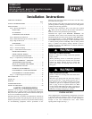
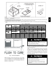
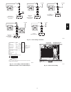
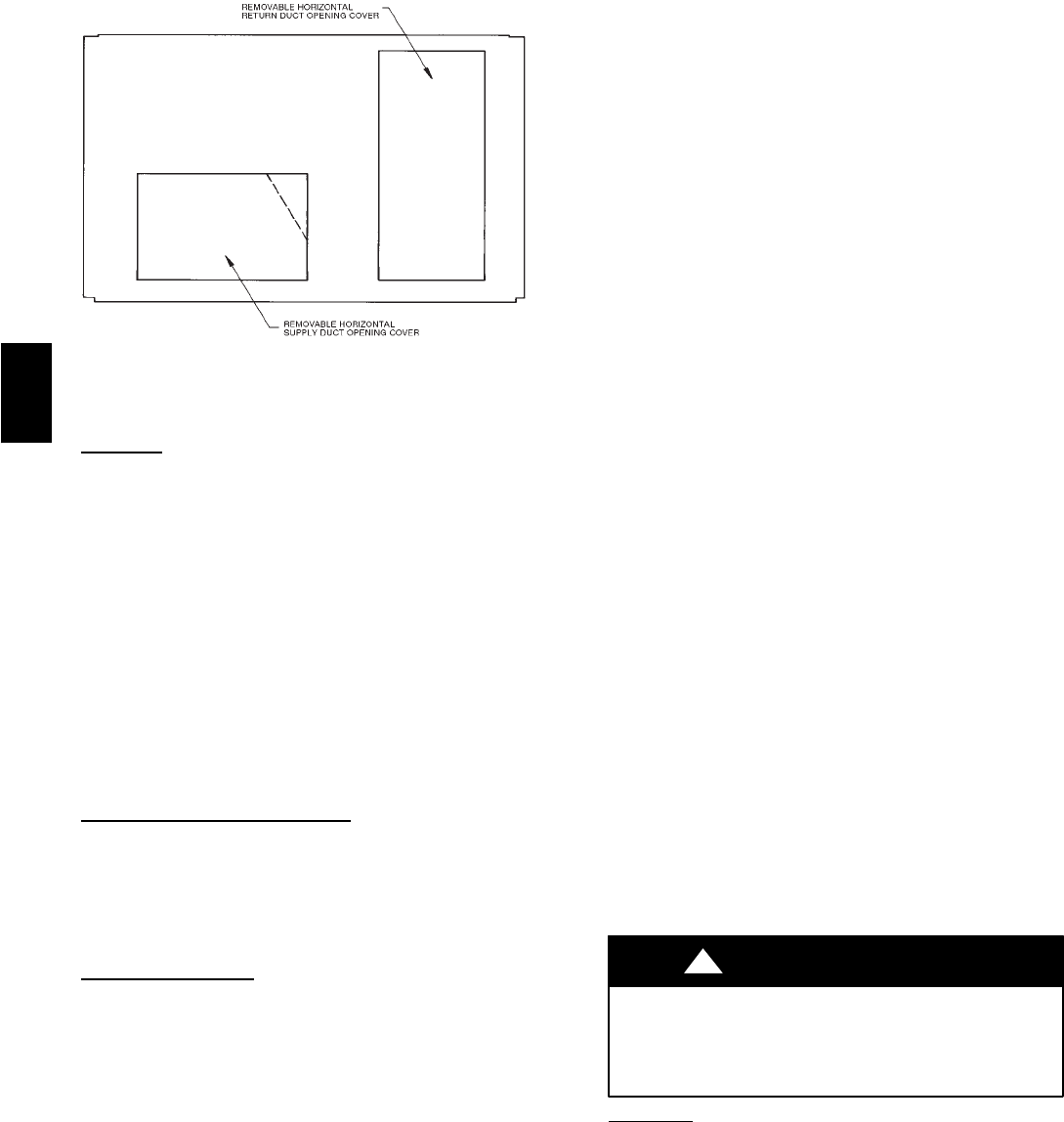
Fig. 1 --- Horizontal Conversion Panels
Step 1 —Provide Unit Support
Roof Curb
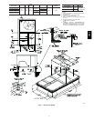
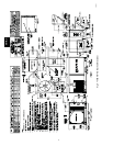
Assemble and install accessory roof curb in accordance with
instructions shipped with curb. (See Fig. 2.) Install insulation,
cant strips, roofing felt, and counter flashing as shown. Ductwork
must be attached to curb, not to the unit. If electric c ontrol power
or gas service is to be routed through the basepan, attach the
accessory thru-the-bottom service connections to the basepan in
accordance with the accessory installation instructions.
Connections must be installed before unit is set on roof curb.
IMPORTANT: The gasketing of the unit to the roof curb is
critical for a watertight seal. Install gasket supplied with the roof
curb as shown in Fig. 2. Improperly applied gasket can result in
air leaks and poor unit performance.
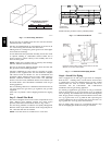
Curb should be level. Unit leveling tolerances are shown in Fig.
3. This is necessary for unit drain to function properly. Refer to
Accessory Roof Curb Installation Instructions for additional
information as required.
Slab Mount (Horizontal Units
Only)
Provide a level concrete slab that extends a minimum of 6 in.
beyond unit cabinet. Install a gravel apron in front of
condenser-coil air inlet to prevent grass and foliage from
obstructing airflow.
NOTE: Horizontal units may be installed on a roof curb if
required.
Alternate Unit
Support
When the curb or adapter cannot be used, support unit with
sleeper rails using unit curb or adapter support area. If sleeper
rails cannot be used, support the long sides of the unit with a
minimum of 3 equally spaced 4-in. x 4-in. pads on each side.
Step 2 —Field Fabricate Ductwork
Secure all ducts to roof curb and building structure on vertical
discharge units. Do not connect ductwork to unit. For horizontal
applications, field-supplied isolation flanges should be attached to
horizontal discharge openings and all ductwork should be secured
to the flanges. Insulate and weatherproof all external ductwork,
joints, and roof openings with counter flashing and mastic in
accordance with applicable codes.
Ducts passing through an unconditioned space must be insulated
and covered with a vapor barrier.
If a plenum return is used on a vertical unit, the return should be
ducted through the roof deck to comply with applicable fire
codes.
A minimum clearance is not required around ductwork. Cabinet
return-air static pressure (a negative condition) shall not exceed
0.35 in. wg with economizer or 0.45 in. wg without economizer.
These units are designed for a minimum continuous return-air
temperature in heating of 50_F (dry bulb), or an intermittent
operation down to 45_F (dry bulb), such as when used with a
night setback thermostat.
To operate at lower r eturn-air temperatures, a field-supplied
outdoor air temperature control must be used to initiate both
stages of heat when the temperature is below 45_F. Indoor
comfort may be compromised when these lower air temperatures
are used with insufficient heating temperature rise.
Step 3 —Install External Trap for Condensate
Drain
The unit’s
3
/
4
-in. condensate drain connections are located on the
bottom and side of the unit. Unit discharge connections do not
determine the use of drain connections; either drain connection
can be used with vertical or horizontal applications.
When using the standard side drain connection, ensure the plug
(Red) in the alternate bottom connection is tight before installing
the unit.
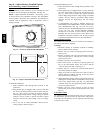
To use the bottom drain connection for a roof curb installation,
relocate the factory-installed plug (Red) from the bottom
connection to the side connection. The center drain plug looks
like a star connection, however it can be removed with a
1
/
2
-in.
socket drive extension. (See Fig. 4.) The piping for the
condensate drain and external trap can be completed after the unit
is in place.
All units must have an external trap for condensate drainage.
Install a trap 4-in. deep and protect against freeze-up. If drain line
is installed downstream from the external trap, pitch the line away
from the unit at 1 in. per 10 ft of run. Do not use a pipe size
smaller than the unit connection (
3
/
4
in.). (See Fig. 5.)
Step 4 —Rig and Place Unit
Inspect unit for transportation damage, and file any claim with
transportation agency. Keep unit upright and do not drop.
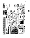
Spreader bars are not required if top crating is left on unit, and
rollers may be used to move unit across a roof. Level by using
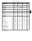
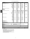
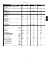
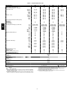
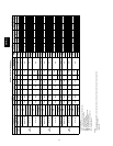
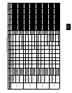
unit frame as a reference. See Table 1 and 2 and Fig. 6 for
additional information. Operating weight is shown in Table 1 and
2 and Fig. 6.
Lifting holes are provided in base rails as shown in Fig. 8 and 9.
Refer to rigging instructions on unit.
PROPERTY DAMAGE HAZARD
Failure to follow this warning could result in personal
injury, death and property damage.
All panels must be in place when rigging and lifting.
!
WARNING
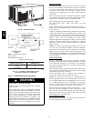
Positioning
Maintain clearance around and above unit to provide minimum
distance from combustible materials, proper airflow, and service
access. (See Fig. 7, 8 and 9.)
Position unit on roof curb so that the following clearances are
maintained:
1
/
4
in. clearance between the roof curb and the base
rail inside the front and rear, 0.0 in. clearance between the roof
curb and the base rail inside on the duct end of the unit. This will
result in the distance between the roof curb and the base rail
inside on the condenser end of the unit being approximately
equal to Fig. 2, section C-C.
Do not install unit in an indoor location. Do not locate unit air
inlets near exhaust vents or other sources of contaminated air.
581B,C