


16
Step 8 —Adjust Factory--Installed Options
Perfect Humidity Adaptive Dehumidification
System
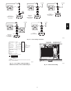
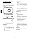
Perfect Humidity system operation can be controlled by field
installation of a Bryant--approved humidistat. (See Fig. 15.)
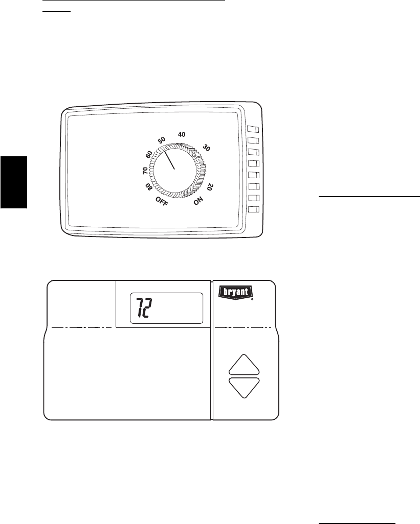
NOTE: A light commercial Thermidistat device (Fig. 16) can
be used instead of the humidistat if desired. The Thermidistat
device includes a thermostat and a humidistat. The humidistat is
normally used in applications where a temperature sensor is
already provided.
%RELATIVEHUMIDITY
C06358
Fig. 15 --- Accessory Field--Installed Humidistat
C06359
Fig. 16 --- Light Commercial Thermidistat Device
To install the humidistat:
1. Route humidistat cable through hole provided in unit
control box.
2. Some models may be equipped with a raceway built into
the corner post located on the left side of control box (See
Fig. 14). T his raceway provides the required clearance
between high--voltage and low voltage wiring. For models
without a raceway, ensure to provide the NEC required
clearance between the high--voltage and low--voltage
wiring.
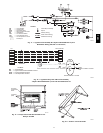
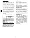
3. Use a wire nut to connect humidistat cable into low-
voltage wiring as shown in Fig. 17.
To install Thermidistat device:
1. Route Thermidistat cable through hole provided in unit
control box.
2. Some models may be equipped with a raceway built into
the corner post located on the left side of control box (See
Fig. 14). T his raceway provides the required clearance
between high--voltage and low voltage wiring. For models
without a raceway, ensure to provide the NEC required
clearance between the high--voltage and low--voltage
wiring.
3. A field-supplied relay must be installed between the
Thermidistat and the Humidi-Mizer circuit (recommended
relay: HN61KK324). (See Fig. 18.) The relay coil is
connected between the DEHUM output and C (common)
of the unit. The relay controls thePerfect Humidity
solenoid valve and must be wired between the Perfect
Humidity fuse and the low-pressure switch. Refer to the
installation instructions included with the Bryant Light
Commercial Thermidistat device for more information.
Manual Outdoor
Damper
The outdoor-- air hood and screen are attached to the basepan at
the bottom of the unit for shipping.
Assembly:
1. Determine quantity of ventilation required for building.
Record amount for use in Step 8.
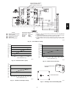
2. Remove and save outdoor air opening panel and screws.
(See Fig. 19.)
3. Remove evaporator coil access panel. Separate hood and
screen from basepan by removing the 4 screws securing
them. Save all screws.
4. Replace evaporator coil access panel.
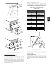
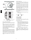
5. Place hood on front of outdoor air opening panel. See
Fig. 20 for hood details. Secure top of hood with the
4screwsremovedinStep3.(SeeFig.21.)
6. Remove and save 6 screws (3 on each side) from sides of
the manual outdoor-air damper.
7. Align screw holes on hood with screw holes on side of
manual outdoor-air damper. (See Fig. 28 and 21.) Secure
hood with 6 screws from Step 6.
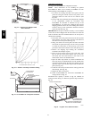
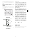
8. Adjust minimum position setting of the damper blade by
adjusting the manual outdoor-air adjustment screws on the
front of the damper blade. (See Fig. 19.) Slide blade
vertically until it is in the appropriate position determined
by Fig. 22. Tighten screws.
9. Remove and save screws currently on sides of hood.
Insert screen. Secure screen to hood using the screws. (See
Fig. 21.)
Convenience
Outlet
An optional convenience outlet provides power for rooftop use.
For maintenance personnel safety, the convenience outlet power
is off when the unit disconnect is off. Adjacent unit outlets may
be used for service tools.
581B,C