


—9—
VII. STEP 7 — MAKE ELECTRICAL CONNECTIONS
A. Field Power Supply
All units except 208/230-v units are factory wired for the
voltage shown on the nameplate. If the 208/230-v unit is to
be connected to a 208-v power supply, the transformer must
be rewired by moving the black wire from the 230-v terminal
on the transformer and connecting it to the 200-v terminal
on the transformer.
Refer to unit label diagram for additional information. Pig-
tails are provided for field service. Use factory-supplied
splices or UL (Underwriters’ Laboratories) approved copper
connector.
When installing units, provide a disconnect per NEC.
All field wiring must comply with NEC and local require-
ments. In Canada, electrical connections must be in accor-
dance with CSA (Canadian Standards Association) C22.1
Canadian Electrical Code Part One.
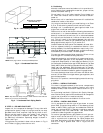
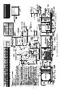
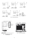
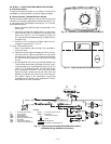
Install conduit through side panel openings indicated in
Fig. 7. Route power lines through connector to terminal
connections as shown in Fig. 10.
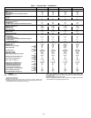
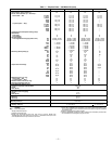
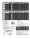
On 3-phase units, voltages between phases must be balanced
within 2% and the current within 10%. Use the formula
shown in Note 3 under Tables 2A-2D to determine the per-
centage of voltage imbalance. Operation on improper line
voltage or excessive phase imbalance constitutes abuse and
may cause damage to electrical components. Such operation
would invalidate any applicable Bryant warranty.
NOTE: If thru-the-bottom accessory connections are used,
refer to the thru-the-bottom accessory installation instruc-
tions for power wiring. Refer to Fig. 7 for location to drill
holes in basepan.
B. Field Control Wiring
Install a Bryant-approved accessory thermostat assembly
according to installation instructions included with the
accessory. Locate thermostat assembly on a solid wall in the
conditioned space to sense average temperature in accor-
dance with thermostat installation instructions.
Route thermostat cable or equivalent single leads of colored
wire from thermostat subbase terminals to low-voltage con-
nections on unit (shown in Fig. 11) as described in Steps 1-4
below.
1. If mounted on a roof curb and electrical power is to be
run through the basepan, an accessory thru-the-bot-
tom connection kit is required. This is available
through the local Bryant distributor. This kit is
required to ensure a reliable water-tight connection.
2. If unit is mounted on roof curb and accessory thru-
the-bottom connections are used, route wire through
connection plate.
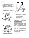
3. Pass control wires through the hole provided on unit
(see connection D, Connection Sizes table, Fig. 7).
4. Feed wires through the raceway built into the corner
post to the 24-v barrier located on the left side of the
control box. See Fig. 12. The raceway provides the
UL-required clearance between high- and low-voltage
wiring.
5. Connect thermostat wires to screw terminals of low-
voltage connection board (see Fig. 11).
NOTE: For wire runs up to 50 ft, use no. 18 AWG (American
Wire Gage) insulated wire (35 C minimum). For 51 to 75 ft,
use no. 16 AWG insulated wire (35 C minimum). For over
75 ft, use no. 14 AWG insulated wire (35 C minimum).
NOTE: All wire larger than no. 18 AWG cannot be directly
connected to the thermostat and will require a junction box
and splice at the thermostat.
C. Heat Anticipator Settings
Set heat anticipator settings at 0.14 amp for first stage and
0.14 amp for second-stage heating, when available.
WARNING: Unit cabinet must have an uninter-
rupted, unbroken electrical ground to minimize the
possibility of personal injury if an electrical fault
should occur. This ground may consist of electrical wire
connected to unit ground lug in control compartment,
or conduit approved for electrical ground when
installed in accordance with NEC (National Electrical
Code), ANSI/NFPA (National Fire Protection Associa-
tion), latest edition, and local electrical codes. Do not
use gas piping as an electrical ground. Failure to follow
this warning could result in the installer being liable
for personal injury of others.
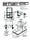
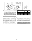
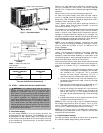
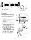
Fig. 8 — Flue Hood Details
LEGEND
*Field supplied.
NOTE: Follow all local codes.
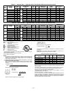
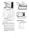
Fig. 9 — Gas Piping Guide (With Accessory
Thru-the-Curb Service Connections)
NFGC — National Fuel Gas Code
STEEL PIPE
NOMINAL DIAMETER
(in.)
SPACING OF SUPPORTS
X DIMENSION
(ft)
1
/
2
3
/
4
or 1
1
1
/
4
or larger
6
8
10