


—22—
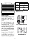
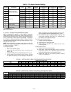
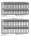
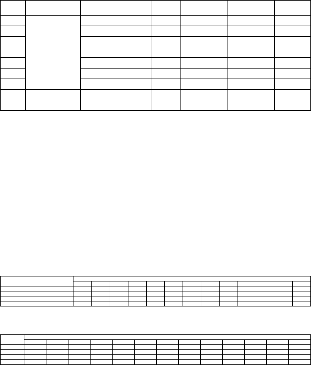
Table 5 — CO
2
Sensor Standard Settings
LEGEND
ppm — Parts Per Million
IX. STEP 9 — ADJUST EVAPORATOR-FAN SPEED
Adjust evaporator-fan speed to meet jobsite conditions.
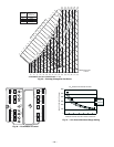
Tables 6A and 6B show fan rpm at motor pulley settings for
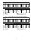
standard and alternate motors. Tables 7 and 8 show evapora-
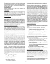
tor fan motor data. Table 9 shows EconoMi$er IV pressure
drop. Table 10 shows sound data. Refer to Tables 11-28 for
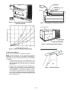
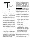
fan performance data. See Fig. 38 for Perfect Humidity™ sys-
tem static pressure drop.
NOTE: Before adjusting fan speed, make sure the new fan
speed will provide an acceptable air temperature rise range
on heating as shown in Table 1.
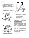
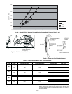
To change fan speed:
1. Shut off unit power supply.
2. Loosen belt by loosening fan motor mounting nuts.
See Fig. 39.
3. Loosen movable pulley flange setscrew (see Fig. 40).
4. Screw movable flange toward fixed flange to increase
fan speed and away from fixed flange to decrease fan
speed. Increasing fan speed increases load on motor.
Do not exceed maximum speed specified in Table 1.
5. Set movable flange at nearest keyway of pulley hub
and tighten setscrew. (See Table 1 for speed change
for each full turn of pulley flange.)
To align fan and motor pulleys:
1. Loosen fan pulley setscrews.
2. Slide fan pulley along fan shaft.
3. Make angular alignment by loosening motor from
mounting plate.
To adjust belt tension:
1. Loosen fan motor mounting nuts.
2. Slide motor mounting plate away from fan scroll for
proper belt tension (
1
/
2
-in. deflection with 8 to 10 lb of
force) and tighten mounting nuts (see Fig. 39).
3. Adjust bolt and nut on mounting plate to secure
motor in fixed position.
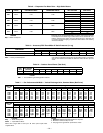
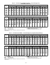
Table 6A — 581B Fan Rpm at Motor Pulley Setting With Standard Motor*
*Approximate fan rpm shown (standard motor/drive).
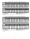
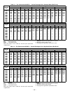
Table 6B — 581B Fan Rpm at Motor Pulley Setting With High-Static Motor*
*Approximate fan rpm shown (high-static motor/drive).
SETTING EQUIPMENT OUTPUT
VENTILATION
RATE
(cfm/Person)
ANALOG
OUTPUT
CO
2
CONTROL RANGE
(ppm)
OPTIONAL
RELAY SETPOINT
(ppm)
RELAY
HYSTERESIS
(ppm)
1
Interface w/Standard
Building Control System
Proportional Any
0-10V
4-20 mA
0-2000 1000 50
2 Proportional Any
2-10V
7-20 mA
0-2000 1000 50
3 Exponential Any
0-10V
4-20 mA
0-2000 1100 50
4
Economizer
Proportional 15
0-10V
4-20 mA
0-1100 1100 50
5 Proportional 20
0-10V
4-20 mA
0- 900 900 50
6 Exponential 15
0-10V
4-20 mA
0-1100 1100 50
7 Exponential 20
0-10V
4-20 mA
0- 900 900 50
8 Health & Safety Proportional —
0-10V
4-20 mA
0-9999 5000 500
9
Parking/Air Intakes/
Loading Docks
Proportional —
0-10V
4-20 mA
0-2000 700 50
UNIT
581B
MOTOR PULLEY TURNS OPEN
0
1
/
2
11
1
/
2
22
1
/
2
33
1
/
2
44
1
/
2
55
1
/
2
6
036 1044 1008 971 935 898 862 826 789 753 716 680 — —
048 1185 1144 1102 1061 1019 978 936 895 853 812 770 — —
060 (single and 3-phase) 1460 1425 1389 1354 1318 1283 1248 1212 1177 1141 1106 1070 1035
072 1585 1538 1492 1445 1399 1352 1305 1259 1212 1166 1119 — —
UNIT
581B
MOTOR PULLEY TURNS OPEN
0
1
/
2
11
1
/
2
22
1
/
2
33
1
/
2
44
1
/
2
55
1
/
2
6
036 1455 1423 1392 1360 1328 1297 1265 1233 1202 1170 1138 1107 1075
048 1455 1423 1392 1360 1328 1297 1265 1233 1202 1170 1138 1107 1075
060 1685 1589 1557 1525 1493 1460 1428 1396 1364 1332 1300 — —
072 1685 1589 1557 1525 1493 1460 1428 1396 1364 1332 1300 — —