


—17—
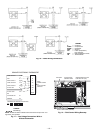
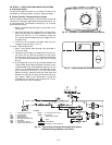
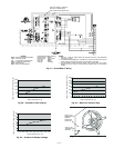
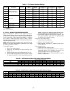
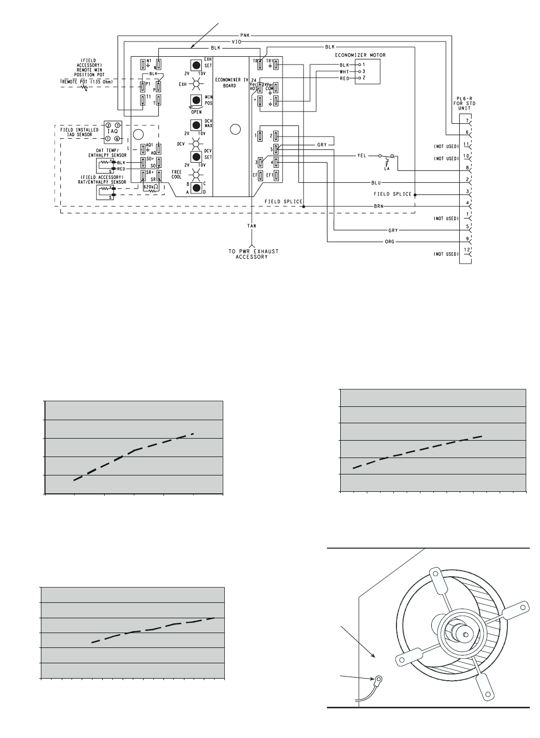
FOR OCCUPANCY CONTROL
REPLACE JUMPER WITH
FIELD-SUPPLIED TIME CLOCK
LEGEND
DCV— Demand Controlled Ventilation
IAQ — Indoor Air Quality
LA — Low Ambient Lockout Device
OAT — Outdoor-Air Temperature
POT— Potentiometer
RAT— Return-Air Temperature
Potentiometer Defaults Settings:
Power Exhaust Middle
Minimum Pos. Fully Closed
DCV Max. Middle
DCV Set Middle
Enthalpy C Setting
NOTES:
1. 620 ohm, 1 watt 5% resistor should be removed only when using differential
enthalpy or dry bulb.
2. If a separate field-supplied 24 v transformer is used for the IAQ sensor power
supply, it cannot have the secondary of the transformer grounded.
3. For field-installed remote minimum position POT, remove black wire jumper
between P and P1 and set control minimum position POT. to the minimum
position.
Fig. 27 — EconoMi$er IV Wiring
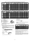
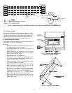
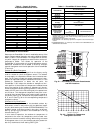
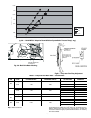
0
1000
2000
3000
4000
5000
6000
0.05 0.10 0.15 0.20 0.25 0.30 0.35
STATIC PRESSURE (in. wg)
FLOW IN CUBIC FEET PER MINUTE (cfm)
Fig. 30 — Return-Air Pressure Drop
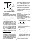
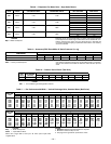
0
500
1000
1500
2000
2500
0.05
0.15
0.25
STATIC PRESSURE (in. wg)
FLOW IN CUBIC FEET PER MINUTE (cfm)
0
5
10
15
20
25
30
0.13 0.20 0.22 0.25 0.30 0.35 0.40 0.45 0.50
STATIC PRESSURE (in. wg)
FLOW IN CUBIC FEET PER MINUTE (cfm)
Fig. 28 — Barometric Flow Capacity
Fig. 29 — Outdoor-Air Damper Leakage
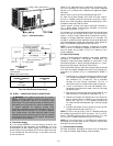
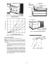
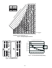
SUPPLY AIR
TEMPERATURE
SENSOR
MOUNTING
LOCATION
SUPPLY AIR
TEMPERATURE
SENSOR
Fig. 31 — Supply Air Sensor Location