


—2—
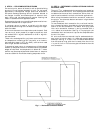
II. STEP 2 — FIELD FABRICATE DUCTWORK
On vertical units, secure all ducts to roof curb and building
structure. Do not connect ductwork to unit. For horizontal
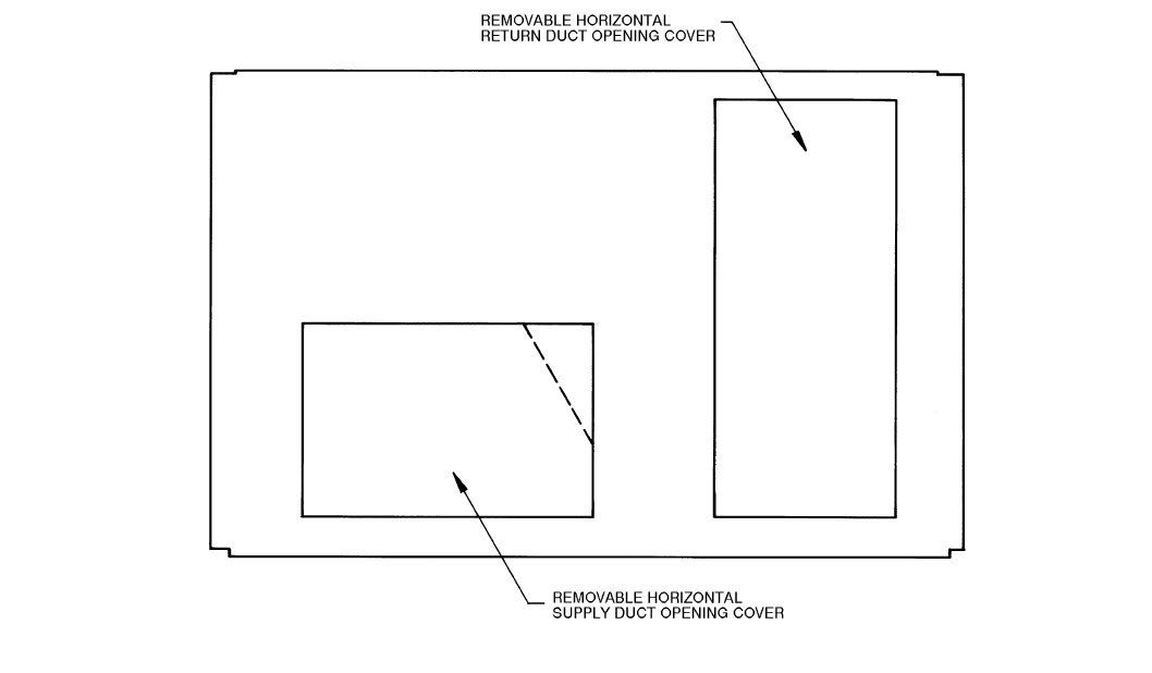
applications, field-supplied flanges should be attached to
horizontal discharge openings and all ductwork secured to
the flanges. Insulate and weatherproof all external duct-
work, joints, and roof openings with counter flashing and
mastic in accordance with applicable codes.
Ducts passing through an unconditioned space must be insu-
lated and covered with a vapor barrier.
If a plenum return is used on a vertical unit, the return
should be ducted through the roof deck to comply with appli-
cable fire codes.
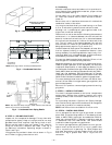
A minimum clearance is not required around ductwork. Cab-
inet return-air static pressure (a negative condition) shall
not exceed 0.35 in. wg with economizer or 0.45 in. wg with-
out economizer.
These units are designed for a minimum continuous return-
air temperature in heating of 50 F (dry bulb), or an intermit-
tent operation down to 45 F (dry bulb), such as when used
with a night set-back thermostat.
To operate at lower return-air temperatures, a field-supplied
outdoor-air temperature control must be used to initiate both
stages of heat when the temperature is below 45 F. Indoor
comfort may be compromised when these lower air tempera-
tures are used with insufficient heating temperature rise.
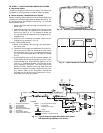
III. STEP 3 — DETERMINE LOCATION OF DRAIN LINE AND
EXTERNAL TRAP
The unit’s
3
/
4
-in. condensate drain connections are located on
the bottom and end of the unit. Unit discharge connections do
not determine the use of drain connections; either drain con-
nection can be used with vertical or horizontal applications.
When using the standard end drain connection, make sure
the plug in the alternate bottom connection is tight before
installing the unit.
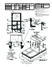
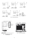
To use the bottom drain connection for a roof curb installa-
tion, relocate the factory-installed plug from the bottom con-
nection to the end connection. The center drain plug looks
like a star connection, however it can be removed with a
1
/
2
-in. socket drive extension. See Fig. 4. The piping for the
condensate drain and external trap can be completed after
the unit is in place.
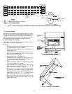
All units must have an external trap for condensate drain-
age. Install a trap at least 4 in. deep and protect against
freeze-up. See Fig. 5. If drain line is installed downstream
from the external trap, pitch the line away from the unit at
1 in. per 10 ft of run. Do not use a pipe size smaller than the
unit connection.
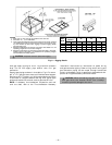
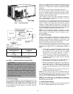
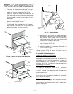
Fig. 1 — Horizontal Conversion Panels