


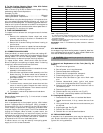
—42—
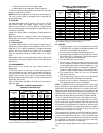
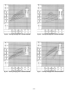
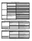
E. To Use Cooling Charging Charts, Units With Perfect
Humidity™ Dehumidification System
Refer to charts (Fig. 52-55) to determine the proper leaving
condenser pressure and temperature.
Example (Fig. 52):
Leaving Condenser Pressure. . . . . . . . . . . . . . . . . . . .250 psig
Leaving Condenser Temperature . . . . . . . . . . . . . . . . . .105 F
NOTE: When using the charging charts, it is important that
only the subcooling/reheat dehumidification coil liquid line
solenoid valve be energized. The subcooling/reheat dehumid-
ification coil liquid line solenoid valve MUST be energized to
use the charging charts and the outdoor motor speed control-
ler jumpered to run the fan at full speed.
X. FLUE GAS PASSAGEWAYS
To inspect the flue collector box and upper areas of the heat
exchanger:
1. Remove the combustion blower wheel and motor
assembly according to directions in Combustion-Air
Blower section following.
2. Remove the 3 screws holding the blower housing to
the flue cover.
3. Remove the flue cover to inspect the heat exchanger.
4. Clean all surfaces as required using a wire brush.
XI. COMBUSTION-AIR BLOWER
Clean periodically to ensure proper airflow and heating effi-
ciency. Inspect blower wheel every fall and periodically during
heating season. For the first heating season, inspect blower
wheel bimonthly to determine proper cleaning frequency.
To inspect blower wheel, remove draft hood and screen.
Shine a flashlight into opening to inspect wheel. If cleaning
is required, remove motor and wheel as follows:
1. Slide burner access panel out.
2. Remove the 5 screws that attach induced-draft motor
assembly to the vestibule cover.
3. Slide the motor and blower wheel assembly out of the
blower housing. The blower wheel can be cleaned at
this point. If additional cleaning is required, continue
with Steps 4 and 5.
4. To remove blower from the motor shaft, by remove
2 setscrews.
5. To remove motor, remove the 4 screws that hold the
motor to mounting plate. Remove the motor cooling
fan by removing one setscrew. Then remove nuts that
hold motor to mounting plate.
6. To reinstall, reverse the procedure outlined above.
XII. LIMIT SWITCH
Remove blower access panel (Fig. 7). Limit switch is located
on the fan deck.
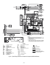
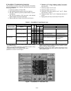
XIII. BURNER IGNITION
Unit is equipped with a direct spark ignition 100% lockout
system. Integrated Gas Unit Controller (IGC) is located in
the control box (Fig. 12). A single LED on the IGC provides a
visual display of operational or sequential problems when
the power supply is uninterrupted. The LED can be observed
through the viewport. When a break in power occurs, the
IGC will be reset (resulting in a loss of fault history) and the
evaporator fan on/off times delay will be reset. During servic-
ing, refer to the label on the control box cover or Table 31 for
an explanation of LED error code descriptions.
If lockout occurs, unit may be reset by interrupting power
supply to unit for at least 5 seconds.
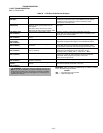
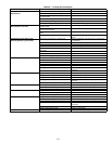
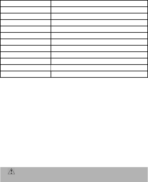
Table 31 — LED Error Code Description*
LEGEND
LED — Light-Emitting Diode
*A 3-second pause exists between LED error code flashes. If more
than one error code exists, all applicable codes will be displayed in
numerical sequence.
†Indicates a code that is not an error. The unit will continue to operate
when this code is displayed.
IMPORTANT: Refer to Troubleshooting Tables 32-36 for additional
information.
XIV. MAIN BURNERS
At the beginning of each heating season, inspect for deteriora-
tion or blockage due to corrosion or other causes. Observe the
main burner flames and adjust, if necessary.
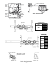
A. Removal and Replacement of Gas Train (See Fig. 56
and 57)
1. Shut off manual gas valve.
2. Shut off power to unit tag disconnect.
3. Remove compressor access panel.
4. Slide out burner compartment side panel.
5. Disconnect gas piping at unit gas valve.
6. Remove wires connected to gas valve. Mark each
wire.
7. Remove induced-draft motor, ignitor, and sensor
wires at the Integrated Gas Unit Controller (IGC).
8. Remove the 2 screws that attach the burner rack to
the vestibule plate.
9. Remove the gas valve bracket.
10. Slide the burner tray out of the unit (Fig. 57).
11. To reinstall, reverse the procedure outlined above.
B. Cleaning and Adjustment
1. Remove burner rack from unit as described above.
2. Inspect burners and, if dirty, remove burners from
rack.
3. Using a soft brush, clean burners and cross-over port
as required.
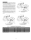
4. Adjust spark gap. See Fig. 58.
5. Reinstall burners on rack.
6. Reinstall burner rack as described above.
XV. REPLACEMENT PARTS
A complete list of replacement parts may be obtained from
your Bryant distributor upon request. Refer to Fig. 59 for a
typical unit wiring schematic.
LED INDICATION ERROR CODE DESCRIPTION
ON Normal Operation
OFF Hardware Failure
1 Flash† Evaporator Fan On/Off Delay Modified
2 Flashes Limit Switch Fault
3 Flashes Flame Sense Fault
4 Flashes 4 Consecutive Limit Switch Faults
5 Flashes Ignition Lockout Fault
6 Flashes Induced-Draft Motor Fault
7 Flashes Rollout Switch Fault
8 Flashes Internal Control Fault
9 Flashes Software Lockout
CAUTION: When working on gas train, do not hit
or plug orifice spuds.