


—36—
A. To Shut Off Unit
Set system selector switch at off position. Resetting heating
selector lever below room temperature will temporarily shut
unit off until space temperature falls below thermostat setting.
XIII. SAFETY RELIEF
A soft-solder joint at the suction service Schrader port
provides pressure relief under abnormal temperature and
pressure conditions.
XIV. VENTILATION (Continuous Fan)
Set fan and system selector switches at ON and OFF posi-
tions, respectively. Evaporator fan operates continuously to
provide constant air circulation. When the evaporator-fan
selector switch is turned to the OFF position, there is a
30-second delay before the fan turns off.
XV. OPERATING SEQUENCE
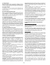
A. Cooling, Units Without Economizer
When thermostat calls for cooling, terminals G and Y1 and
the compressor contactor (C) are energized. The indoor
(evaporator) fan motor (IFM), compressor, and outdoor (con-
denser) fan motor (OFM) start. The OFM runs continuously
while the unit is in cooling. When the thermostat is satisfied,
C is deenergized and the compressor and OFM shut off. After
a 30-second delay, the IFM shuts off. If the thermostat fan
selector switch is in the ON position, the evaporator motor
will run continuously.
B. Heating, Units Without Economizer
When the thermostat calls for heating, terminal W1 is ener-
gized. The induced-draft motor is energized and the burner
ignition sequence begins. The indoor (evaporator) fan motor
(IFM) is energized 45 seconds after a flame is ignited. When
additional heat is needed, W2 is energized and the high-fire
solenoid on the main gas valve (MGV) is energized. When
the thermostat is satisfied and W1 is deenergized, the IFM
stops after a 45-second time-off delay.
C. Cooling, Units With EconoMi$er IV
When free cooling is not available, the compressors will be
controlled by the zone thermostat. When free cooling is avail-
able, the outdoor-air damper is modulated by the
EconoMi$er IV control to provide a 50 to 55 F supply-air
temperature into the zone. As the supply-air temperature
fluctuates above 55 or below 50 F, the dampers will be modu-
lated (open or close) to bring the supply-air temperature
back within the set points.
Integrated EconoMi$er IV operation on single-stage units
requires a 2-stage thermostat (Y1 and Y2).
For EconoMi$er IV operation, there must be a thermostat
call for the fan (G). This will move the damper to its mini-
mum position during the occupied mode.
If the increase in cooling capacity causes the supply-air tem-
perature to drop below 45 F, then the outdoor-air damper
position will be fully closed. If the supply-air temperature
continues to fall, the outdoor-air damper will close. Control
returns to normal once the supply-air temperature rises
above 48 F.
If optional power exhaust is installed, as the outdoor-air
damper opens and closes, the power exhaust fans will be
energized and deenergized.
If field-installed accessory CO
2
sensors are connected to the
EconoMi$er IV control, a demand controlled ventilation
strategy will begin to operate. As the CO
2
level in the zone
increases above the CO
2
set point, the minimum position of
the damper will be increased proportionally. As the CO
2
level
decreases because of the increase in fresh air, the outdoor-air
damper will be proportionally closed. Damper position will
follow the higher demand condition from DCV mode or free
cooling mode.
Damper movement from full closed to full open (or vice
versa) will take between 1
1
/
2
and 2
1
/
2
minutes.
If free cooling can be used as determined from the appropri-
ate changeover command (switch, dry bulb, enthalpy curve,
differential dry bulb, or differential enthalpy), a call for cool-
ing (Y1 closes at the thermostat) will cause the control to
modulate the dampers open to maintain the supply air tem-
perature set point at 50 to 55 F.
As the supply-air temperature drops below the set point range
of 50 to 55 F, the control will modulate the outdoor-air damp-
ers closed to maintain the proper supply-air temperature.
D. Heating, Units With EconoMi$er IV
When the room temperature calls for heat, the heating con-
trols are energized as described in the Heating, Units With-
out Economizer section. When the thermostat is satisfied,
the economizer damper moves to the minimum position.
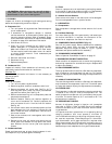
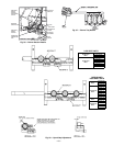
E. Units With Perfect Humidity™ Dehumidification
System
Normal Design Cooling Operation
When the rooftop operates under the normal sequence of
operation, the compressors will cycle to maintain indoor con-
ditions. See Fig. 41.
The Perfect Humidity adaptive dehumidification system
includes a factory-installed Motormaster® low ambient con-
trol to keep the head and suction pressure high, allowing
normal design cooling mode operation down to 0° F.
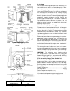
Subcooling Mode
When subcooling mode is initiated, this will energize (close)
the liquid line solenoid valve (LLSV) forcing the hot liquid
refrigerant to enter the subcooling coil (see Fig. 42).
As the hot liquid refrigerant passes through the subcooling/
reheat dehumidification coil, it is exposed to the cold supply
airflow coming through the evaporator coil. The liquid is fur-
ther subcooled to a temperature approaching the evaporator
leaving-air temperature. The liquid then enters a thermostatic
expansion valve (TXV) where the liquid drops to a lower pres-
sure. The TXV does not have a pressure drop great enough to
change the liquid to a 2-phase fluid, so the liquid then enters
the Acutrol™ device at the evaporator coil.
The liquid enters the evaporator coil at a temperature lower
than in standard cooling operation. This lower temperature
increases the latent capacity of the rooftop unit. The refriger-
ant passes through the evaporator and is turned into a
vapor. The air passing over the evaporator coil will become
colder than during normal operation. However, as this same
air passes over the subcooling coil, it will be slightly warmed,
partially reheating the air.
Subcooling mode operates only when the outside-air temper-
ature is warmer than 40 F. A factory-installed temperature
switch located in the condenser section will lock out subcool-
ing mode when the outside temperature is cooler than 40 F.
The scroll compressors are equipped with crankcase heaters
to provide protection for the compressors due to the addi-
tional refrigerant charge required by the subcooling/reheat
coil.
When in subcooling mode, there is a slight decrease in sys-
tem total gross capacity (5% less), a lower gross sensible
capacity (20% less), and a greatly increased latent capacity
(up to 40% more).