


—7—
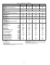
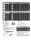
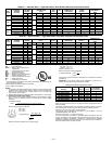
Table 1 — Physical Data — 581B036-072 (cont)
LEGEND
*Single phase/three phase.
†Indicates automatic reset.
**60,000 and 72,000 Btuh heat input units have 2 burners. 90,000 and
120,000 Btuh heat input units have 3 burners. 115,000 Btuh heat input units
and 150,000 Btuh Heat input units have 3 burners.
††An LP kit is available as an accessory. If an LP kit is used with low NO
x
units,
one low NO
x
baffle must be removed and the units will no longer be classified
as low NO
x
units.
||California compliant three-phase models.
***California SCAQMD compliant low NO
x
models have combustion products that
are controlled to 40 nanograms per joule or less.
UNIT SIZE 581B 036 048 060 072
FURNACE SECTION
Rollout Switch Cutout Temp (F)† 195 195 195 195
Burner Orifice Diameter (in. ...drill size)**
Natural Gas — Std 071/072 .113...33 .113...33 .113...33 .113...33
114/115 .113...33 .113...33 .113...33 .113...33
149/150 — .129...30 .129...30 .129...30
060N .102...38 .102...38 .102...38 —
090N .102...38 .102...38 .102...38 —
120N — .116...32 .116...32 —
Liquid Propane — Alt††
071/072 .089...43 .089...43 .089...43 .089...43
114/115 .089...43 .089...43 .089...43 .089...43
149/150 — .102...38 .102...38 .102...38
060N .082...45 .082...45 .082...45 —
090N .082...45 .082...45 .082...45 —
120N — .094...42 .094...42 —
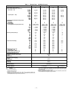
Thermostat Heat Anticipator Setting (amps)
208/230/460 v
First Stage .14 .14 .14 .14
Second Stage .14 .14 .14 .14
Gas Input (Btuh)
First Stage/Second Stage (3-phase units) 072 50,000/ 72,000 50,000/ 72,000 50,000/ 72,000 50,000/ 72,000
115 82,000/115,000 82,000/115,000 82,000/115,000 82,000/115,000
150 — 120,000/150,000 120,000/150,000 120,000/150,000
071II —/ 72,000 —/ 72,000 —/ 72,000 —
114II —/115,000 —/115,000 —/115,000 —
149II — —/150,000 —/150,000 —
060N*** —/ 60,000 —/ 60,000 —/ 60,000 —
090N*** —/ 90,000 —/ 90,000 —/ 90,000 —
120N*** — —/120,000 —/120,000 —
Efficiency (Steady State) (%)
072 82.8 82.8 82.8 82
115 80 81 81 81
150 — 80.4 80.4 80
071 82 82 82 —
114 80 81 81 —
149 —8080—
060N 80.2 80.2 80.2 —
090N 81 81 81 —
120N — 80.7 80.7 —
Temperature Rise Range
072 25-55 25-55 25-55 25-55
115 55-85 35-65 35-65 35-65
150 — 50-80 50-80 50-80
071 25-55 25-55 25-55 —
114 55-85 35-65 35-65 —
149 — 50-80 50-80 —
060N 20-50 20-50 20-50 —
090N 30-60 30-60 30-60 —
120N — 40-70 40-70 —
Manifold Pressure (in. wg)
Natural Gas — Std 3.5 3.5 3.5 3.5
Liquid Propane — Alt†† 3.5 3.5 3.5 3.5
Maximum Static Pressure (in. wg) 1.0 1.0 1.0 1.0
Field Gas Connection Size (in.)
1
/
2
1
/
2
1
/
2
1
/
2
HIGH-PRESSURE SWITCH (psig)
450 ± 50
428
320
Standard Compressor Internal Relief
Cutout
Reset (Auto.)
LOSS-OF-CHARGE SWITCH/LOW-PRESSURE
SWITCH (Liquid LIne) (psig)
7 ± 3
22 ± 5
Cutout
Reset (Auto.)
FREEZE PROTECTION THERMOSTAT
30 ± 5
45 ± 5
Opens (F)
Closes (F)
OUTDOOR-AIR INLET SCREENS
Cleanable
1...20 x 24 x 1
Quantity...Size (in.)
RETURN-AIR FILTERS Throwaway
Quantity...Size (in.) 2...16 x 25 x 2
4...16 x 16 x 2
Bhp—
Brake Horsepower