


—14—
C. Convenience Outlet
An optional convenience outlet provides power for rooftop
use. For maintenance personnel safety, the convenience out-
let power is off when the unit disconnect is off. Adjacent unit
outlets may be used for service tools. An optional “Hot Out-
let” is available from the factory as a special order item.
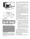
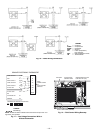
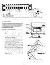
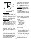
D. Manual Outdoor-Air Damper
The outdoor-air hood and screen are attached to the basepan
at the bottom of the unit for shipping.
Assembly:
1. Determine quantity of ventilation required for build-
ing. Record amount for use in Step 8.
2. Remove outdoor-air opening panel. Save panels and
screws. See Fig. 17.
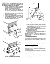
3. Remove evaporator coil access panel. Separate hood
and screen from basepan by removing the 4 screws
securing them. Save all screws.
4. Replace evaporator coil access panel.
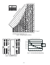
5. Place hood on front of outdoor-air opening panel. See
Fig. 18 for hood details. Secure top of hood with the 4
screws removed in Step 3. See Fig. 19.
6. Remove and save 6 screws (3 on each side) from sides
of the manual outdoor-air damper.
7. Align screw holes on hood with screw holes on side of
manual outdoor-air damper. See Fig. 18 and 19.
Secure hood with 6 screws from Step 6.
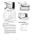
8. Adjust minimum position setting of the damper blade
by adjusting the manual outdoor-air adjustment
screws on the front of the damper blade. See Fig. 17.
Slide blade vertically until it is in the appropriate
position determined by Fig. 20. Tighten screws.
9. Remove and save screws currently on sides of hood.
Insert screens. Secure screens to hood using the
screws. See Fig. 19.
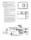
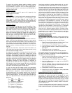
ROOF TOP UNIT
R
C
Y1
Y2
G
W1
W2
PINK
PINK
RED
24 V
FROM
PERFECT HUMIDITY
SYSTEM LLSV
R1
T STAT WIRES
LCT
R
C
Y1
Y2
G
W1
W2
DEHUM
OC
R1
PERFECT HUMIDITY SYSTEM
PINK
LTLO
CB
3.2 AMPS
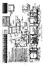
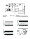
Fig. 16 — Typical Rooftop Unit with Perfect Humidity™ Dehumidification System with Thermidistat Device
LEGEND
CB — Circuit Breaker
LCT — Light Commercial Thermidistat™ Device
LLSV — Liquid Line Solenoid Valve
LTLO — Low Temperature Lockout
OUTDOOR
AIR OPENING
PANEL
3 SCREWS
(SIDE)
Fig. 17 — Damper Panel with Manual
Outdoor-Air Damper Installed
Fig. 18 — Outdoor-Air Hood Details