


—5—
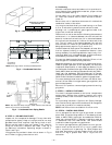
Size gas supply piping for 0.5-in. wg maximum pressure
drop. Do not use supply pipe smaller than unit gas
connection.
Support gas piping as shown in the table in Fig. 9. For exam-
ple, a
3
/
4
-in. gas pipe must have one field-fabricated support
beam every 8 ft. Therefore, an 18-ft long gas pipe would have
a minimum of 3 support beams. See Fig. 9 for typical pipe
guide and locations of external manual gas shutoff valve.
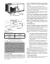
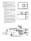
NOTE: If accessory thru-the-bottom connections and roof
curb are used, refer to the Thru-the-Bottom Accessory
Installation Instructions for information on power wiring
and gas connection piping. Power wiring, control wiring and
gas connection piping can be routed through field-drilled
holes in the basepan, which is specifically designed and dim-
pled for drilling the accessory connection holes.
CAUTION: When connecting the gas line to the
unit gas valve, the installer MUST use a backup
wrench to prevent damage to the valve.
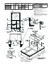
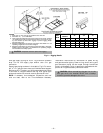
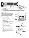
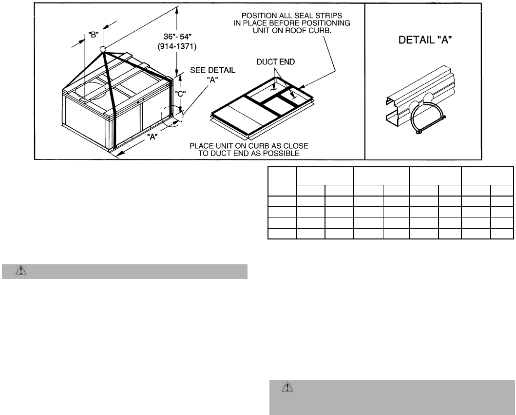
NOTES:
1. Place unit on curb as close as possible to the duct end.
2. Dimension in ( ) is in millimeters.
3. Hook rigging shackles through holes in base rail as shown in detail
“A.” Holes in base rails are centered around the unit center of grav-
ity. Use wooden top skid when rigging to prevent rigging straps
from damaging unit.
4. Weights include base unit without economizer. See Table 1 for unit
operating weights and economizer weights.
5. Weights include base unit without the Perfect Humidity™ dehumid-
ification system. See Table 1 for additional unit operating weights
with the Perfect Humidity system.
CAUTION: All panels must be in place when rigging.
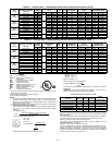
Fig. 6 — Rigging Details
UNIT
581B
OPERATING
WEIGHT
“A” “B” “C”
lb kg in. mm in. mm in. mm
036 530 240 73.69 1872 35.50 902 33.31 847
048 540 245 73.69 1872 35.50 902 33.31 847
060 560 254 73.69 1872 35.50 902 33.31 847
072 635 288 73.69 1872 35.50 902 33.31 847