


—34—
PRE-START-UP
Proceed as follows to inspect and prepare the unit for initial
start-up:
1. Remove all access panels.
2. Read and follow instructions on all WARNING, CAU-
TION, and INFORMATION labels attached to, or
shipped with, unit.
3. Make the following inspections:
a. Inspect for shipping and handling damages such
as broken lines, loose parts, or disconnected
wires, etc.
b. Inspect for oil at all refrigerant tubing connec-
tions and on unit base. Detecting oil generally
indicates a refrigerant leak. Leak-test all refrig-
erant tubing connections using electronic leak
detector, halide torch, or liquid-soap solution.
c. Inspect all field-wiring and factory-wiring con-
nections. Be sure that connections are completed
and tight. Be sure that wires are not in contact
with refrigerant tubing or sharp edges.
d. Inspect coil fins. If damaged during shipping and
handling, carefully straighten fins with a fin
comb.
4. Verify the following conditions:
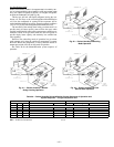
a. Make sure that condenser-fan blade are correctly
positioned in fan orifice. See Condenser-Fan
Adjustment section on page 38 for more details.
b. Make sure that air filter(s) is in place.
c. Make sure that condensate drain trap is filled
with water to ensure proper drainage.
d. Make sure that all tools and miscellaneous loose
parts have been removed.
START-UP
I. UNIT PREPARATION
Make sure that unit has been installed in accordance with
installation instructions and applicable codes.
II. GAS PIPING
Check gas piping for leaks.
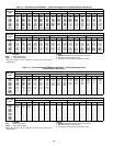
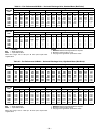
III. RETURN-AIR FILTERS
Make sure correct filters are installed in unit (see Table 1). Do
not operate unit without return-air filters.
IV. OUTDOOR-AIR INLET SCREENS
Outdoor-air inlet screen must be in place before operating
unit.
V. COMPRESSOR MOUNTING
Compressors are internally spring mounted. Do not loosen or
remove compressor holddown bolts.
VI. INTERNAL WIRING
Check all electrical connections in unit control boxes.
Tighten as required.
VII. REFRIGERANT SERVICE PORTS
Each unit system has 4 Schrader-type service ports: one on
the suction line, one on the liquid line, and 2 on the compres-
sor discharge line. Be sure that caps on the ports are tight.
Two additional Schrader valves are located under the high-
pressure and low-pressure switches, respectively.
VIII. HIGH FLOW REFRIGERANT VALVES
Two high flow valves are located on the hot gas tube coming
out of the compressor and the suction tube going into the
compressor. Large black plastic caps identify these valves.
These valves have O-rings inside which screw the cap onto a
brass body to prevent leaks. No field access to these valves is
available at this time. Ensure the plastic caps remain on the
valves and are tight or the possibility of refrigerant leakage
could occur.
IX. COMPRESSOR ROTATION
On 3-phase units with scroll compressors, it is important to
be certain compressor is rotating in the proper direction. To
determine whether or not compressor is rotating in the
proper direction:
1. Connect service gages to suction and discharge pres-
sure fittings.
2. Energize the compressor.
3. The suction pressure should drop and the discharge
pressure should rise, as is normal on any start-up.
If the suction pressure does not drop and the discharge pres-
sure does not rise to normal levels:
1. Note that the evaporator fan (size 060 and 072 only)
is probably also rotating in the wrong direction.
2. Turn off power to the unit and install lockout tag.
WARNING: Failure to observe the following warn-
ings could result in serious personal injury.
1. Follow recognized safety practices and wear
protective goggles when checking or servicing
refrigerant system.
2. Do not operate compressor or provide any elec-
tric power to unit unless compressor terminal
cover is in place and secured.
3. Do not remove compressor terminal cover until
all electrical sources are disconnected.
4. Relieve all pressure from system before touch-
ing or disturbing anything inside terminal box
if refrigerant leak is suspected around compres-
sor terminals.
5. Never attempt to repair soldered connection
while refrigerant system is under pressure.
6. Do not use torch to remove any component. Sys-
tem contains oil and refrigerant under pres-
sure. To remove a component, wear protective
goggles and proceed as follows:
a. Shut off electrical power and then gas to
unit.
b. Recover refrigerant to relieve all pressure
from system using both high-pressure and
low-pressure ports.
c. Cut component connection tubing with tub-
ing cutter and remove component from
unit.
d. Carefully unsweat remaining tubing stubs
when necessary. Oil can ignite when
exposed to torch flame.
WARNING: Disconnect gas piping from unit when
leak testing at pressure greater than
1
/
2
psig. Pres-
sures greater than
1
/
2
psig will cause gas valve damage
resulting in hazardous condition. If gas valve is sub-
jected to pressure greater than
1
/
2
psig, it must be
replaced before use. When pressure testing field-
supplied gas piping at pressures of
1
/
2
psig or less, a
unit connected to such piping must be isolated by man-
ually closing the gas valve.