


—38—
SERVICE
I. CLEANING
Inspect unit interior at the beginning of heating and cooling
season and as operating conditions require.
A. Evaporator Coil
1. Turn unit power off, tag disconnect. Remove evapora-
tor coil access panel.
2. If economizer or two-position damper is installed,
remove economizer by disconnecting Molex plug and
removing mounting screws. Refer to accessory econo-
mizer installation instructions or Optional EconoMi$er
IV section on page 15 for additional information.
3. Slide filters out of unit.
4. Clean coil using a commercial coil cleaner or dish-
washer detergent in a pressurized spray canister.
Wash both sides of coil and flush with clean water.
For best results, back-flush toward return-air section
to remove foreign material. Flush condensate pan
after completion.
5. Reinstall economizer and filters.
6. Reconnect wiring.
7. Replace access panels.
B. Condenser Coil
Inspect coil monthly. Clean condenser coil annually, and as
required by location and outdoor air conditions.
One-Row Coil
Wash coil with commercial coil cleaner. It is not necessary to
remove top panel.
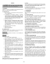
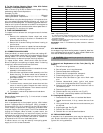
2-Row Coils
Clean coil as follows:
1. Turn off unit power, tag disconnect.
2. Remove top panel screws on condenser end of unit.
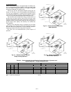
3. Remove condenser coil corner post. See Fig. 44. To
hold top panel open, place coil corner post between
top panel and center post. See Fig. 45.
4. Remove screws securing coil to compressor plate and
compressor access panel.
5. Remove fastener holding coil sections together at
return end of condenser coil. Carefully separate the
outer coil section 3 to 4 in. from the inner coil section.
See Fig. 46.
6. Use a water hose or other suitable equipment to flush
down between the 2 coil sections to remove dirt and
debris. Clean the outer surfaces with a stiff brush in
the normal manner.
7. Secure inner and outer coil rows together with a field-
supplied fastener.
8. Reposition the outer coil section and remove the coil
corner post from between the top panel and center
post. Reinstall the coil corner post and replace all
screws.
C. Condensate Drain
Check and clean each year at start of cooling season. In win-
ter, keep drain dry or protect against freeze-up.
D. Filters
Clean or replace at start of each heating and cooling season,
or more often if operating conditions require it. Replacement
filters must be same dimensions as original filters.
E. Outdoor-Air Inlet Screens
Clean screen with steam or hot water and a mild detergent.
Do not use disposable filters in place of screen.
II. LUBRICATION
A. Compressors
Each compressor is charged with correct amount of oil at the
factory.
B. Fan Motor Bearings
Fan motor bearings are of the permanently lubricated type.
No further lubrication is required. No lubrication of con-
denser-fan or evaporator-fan motors is required.
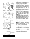
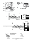
III. CONDENSER-FAN ADJUSTMENT (Fig. 47)
Shut off unit power supply. Remove condenser-fan assembly
(grille, motor, motor cover, and fan) and loosen fan hub
setscrews. Adjust fan height as shown in Fig. 47. Tighten
setscrews and replace condenser-fan assembly.
IV. ECONOMI$ER IV ADJUSTMENT
Refer to Optional EconoMi$er IV section on page 15.
V. EVAPORATOR FAN BELT INSPECTION
Check condition of evaporator belt or tension during heating
and cooling inspections or as conditions require. Replace belt
or adjust as necessary.
VI. HIGH-PRESSURE SWITCH
The high-pressure switch contains a Schrader core depressor,
and is located on the compressor hot gas line. This switch
opens at 428 psig and closes at 320 psig. No adjustments are
necessary.
VII. LOSS-OF-CHARGE SWITCH
The loss-of-charge switch contains a Schrader core depressor,
and is located on the compressor liquid line. This switch opens
at 7 psig and closes at 22 psig. No adjustments are necessary.
VIII. FREEZE-STAT
The freeze-stat is a bimetal temperature-sensing switch that
is located on the “hair-pin” end of the evaporator coil. The
switch protects the evaporator coil from freeze-up due to lack
of airflow. The switch opens at 30 F and closes at 45 F. No
adjustments are necessary.
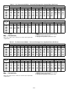
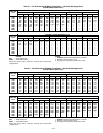
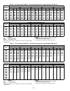
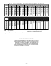
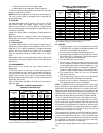
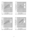
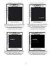
IX. REFRIGERANT CHARGE
Amount of refrigerant charge is listed on unit nameplate
(also refer to Table 1). Refer to HVAC Servicing Procedures
literature available at your local distributor and the follow-
ing procedures.
Unit panels must be in place when unit is operating during
charging procedure. Unit must operate a minimum of
10 minutes before checking or adjusting refrigerant charge.
An accurate superheat, thermocouple-type or thermistor-
type thermometer, and a gage manifold are required when
using the superheat charging method for evaluating the unit
charge. Do not use mercury or small dial-type thermometers
because they are not adequate for this type of measurement.
CAUTION: When servicing unit, shut off all elec-
trical power to unit and install lockout tag to avoid
shock hazard or injury from rotating parts.