


—4—
IV. STEP 4 — RIG AND PLACE UNIT
Inspect unit for transportation damage. File any claim with
transportation agency. Keep unit upright and do not drop.
Spreader bars are not required if top crating is left on unit.
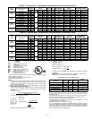
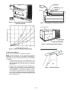
Rollers may be used to move unit across a roof. Level by
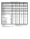
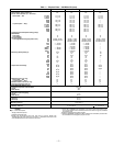
using unit frame as a reference. See Table 1 and Fig. 6
for additional information. Operating weight is shown in
Table 1 and Fig. 6.
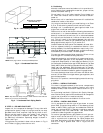
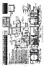
Lifting holes are provided in base rails as shown in Fig. 6
and 7. Refer to rigging instructions on unit.
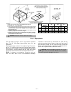
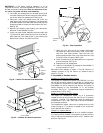
A. Positioning
Maintain clearance around and above unit to provide mini-
mum distance from combustible materials, proper airflow,
and service access. See Fig. 7.
Do not install unit in an indoor location. Do not locate unit
air inlets near exhaust vents or other sources of contami-
nated air.
Be sure that unit is installed so that snow will not block the
combustion intake or flue outlet.
Unit may be installed directly on wood flooring or on Class
A, B, or C roof-covering material when roof curb is used.
Although unit is weatherproof, guard against water from
higher level runoff and overhangs.
Position unit on roof curb so that the following clearances are
maintained:
1
/
4
in. clearance between the roof curb and the
base rail inside the front and rear, 0.0 in. clearance between
the roof curb and the base rail inside on the duct end of the
unit. This will result in the distance between the roof curb
and the base rail inside on the condenser end of the unit
being approximately equal to Fig. 2, section C-C.
Locate mechanical draft system flue assembly at least 48 in.
from an adjacent building or combustible material. Units
having accessory flue discharge deflector require only 18 in.
clearance. When unit is located adjacent to public walkways,
flue assembly must be at least 7 ft above grade.
Flue gas can deteriorate building materials. Orient unit so
that flue gas will not affect building materials.
Adequate combustion and ventilation air space must be pro-
vided for proper operation of this equipment. Be sure that
installation complies with all local codes and Section 5.3, Air
for Combustion and Ventilation per NFGC (National Fuel Gas
Code), ANSI (American National Standards Institute) Z223.1-
latest year and addendum Z223.1A-latest year. In Canada,
installation must be in accordance with the CAN1.B149.1 and
CAN1.B149.2 installation codes for gas burning appliances.
Flue vent discharge must have a minimum horizontal clear-
ance of 4 ft from electric and gas meters, gas regulators, and
gas relief equipment.
After unit is in position, remove shipping materials and rig-
ging skids.
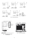
V. STEP 5 — INSTALL FLUE HOOD
Flue hood is shipped screwed to the burner compartment
access panel. Remove from shipping location and, using
screws provided, install flue hood in location shown in Fig. 7
and 8.
For units being installed in California Air Quality Manage-
ment Districts which require NOx emissions of 40 nanograms/
joule or less, a low NOx unit must be installed.
NOTE: Low NOx units are available for 3 to 5 ton units.
VI. STEP 6 — INSTALL GAS PIPING
Unit is equipped for use with type of gas shown on name-
plate. Refer to local building codes, or in the absence of local
codes, to ANSI Z223.1-latest year and addendum Z223.1A-
latest year entitled NFGC. In Canada, installation must be
in accordance with the CAN1.B149.1 and CAN1.B149.2
installation codes for gas burning appliances.
For natural gas applications, gas pressure at unit gas con-
nection must not be less than 4.0 in. wg or greater than
13.0 in. wg while unit is operating. For liquid propane and
high heat applications, the gas pressure must not be less
than 5.0 in. wg or greater than 13.0 in. wg at the unit
connection.
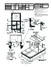
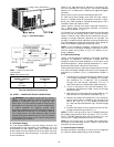
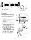
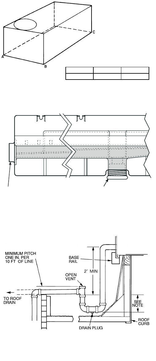
DRAIN PLUGHORIZONTAL
DRAIN PLUG
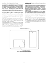
Fig. 3 — Unit Leveling Tolerances
NOTE: Drain plug is shown in factory-installed position.
Fig. 4 — Condensate Drain Pan
NOTE: Trap should be deep enough to offset maximum unit static dif-
ference. A 4-in. trap is recommended.
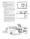
Fig. 5 — Condensate Drain Piping Details
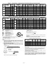
MAXIMUM ALLOWABLE
DIFFERENCE (in.)
A-B B-C A-C
0.5 1.0 1.0