


—21—
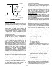
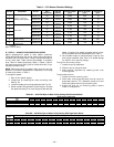
To control the minimum damper position remotely, remove
the factory-installed jumper on the P and P1 terminals on
the EconoMi$er IV controller. Wire the field-supplied poten-
tiometer to the P and P1 terminals on the EconoMi$er IV
controller. See Fig. 36.
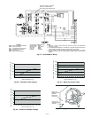
Damper Movement
Damper movement from full open to full closed (or vice
versa) takes 2
1
/
2
minutes.
Thermostats
The EconoMi$er IV control works with conventional thermo-
stats that have a Y1 (cool stage 1), Y2 (cool stage 2), W1
(heat stage 1), W2 (heat stage 2), and G (fan). The
EconoMi$er IV control does not support space temperature
sensors. Connections are made at the thermostat terminal
connection board located in the main control box.
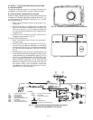
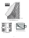
Occupancy Control
The factory default configuration for the EconoMi$er IV con-
trol is occupied mode. Occupied status is provided by the
black jumper from terminal TR to terminal N. When unoccu-
pied mode is desired, install a field-supplied timeclock func-
tion in place of the jumper between TR and N. See Fig. 27.
When the timeclock contacts are closed, the EconoMi$er IV
control will be in occupied mode. When the timeclock con-
tacts are open (removing the 24-v signal from terminal N),
the EconoMi$er IV will be in unoccupied mode.
Demand Controlled Ventilation (DCV)
When using the EconoMi$er IV for demand controlled venti-
lation, there are some equipment selection criteria which
should be considered. When selecting the heat capacity and
cool capacity of the equipment, the maximum ventilation
rate must be evaluated for design conditions. The maximum
damper position must be calculated to provide the desired
fresh air.
Typically the maximum ventilation rate will be about 5 to
10% more than the typical cfm required per person, using
normal outside air design criteria.
A proportional anticipatory strategy should be taken with
the following conditions: a zone with a large area, varied
occupancy, and equipment that cannot exceed the required
ventilation rate at design conditions. Exceeding the required
ventilation rate means the equipment can condition air at a
maximum ventilation rate that is greater than the required
ventilation rate for maximum occupancy. A proportional-
anticipatory strategy will cause the fresh air supplied to
increase as the room CO
2
level increases even though the
CO
2
set point has not been reached. By the time the CO
2
level reaches the set point, the damper will be at maximum
ventilation and should maintain the set point.
In order to have the CO
2
sensor control the economizer
damper in this manner, first determine the damper voltage
output for minimum or base ventilation. Base ventilation is
the ventilation required to remove contaminants during
unoccupied periods. The following equation may be used to
determine the percent of outside-air entering the building for
a given damper position. For best results there should be at
least a 10 degree difference in outside and return-air tem-
peratures.
T
O
= Outdoor-Air Temperature
OA = Percent of Outdoor Air
T
R
= Return-Air Temperature
RA = Percent of Return Air
T
M
= Mixed-Air Temperature
Once base ventilation has been determined, set the mini-
mum damper position potentiometer to the correct position.
The same equation can be used to determine the occupied or
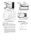
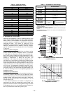
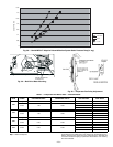
maximum ventilation rate to the building. For example, an
output of 3.6 volts to the actuator provides a base ventilation
rate of 5% and an output of 6.7 volts provides the maximum
ventilation rate of 20% (or base plus 15 cfm per person). Use
Fig. 37 to determine the maximum setting of the CO
2
sensor.
For example, a 1100 ppm set point relates to a 15 cfm per
person design. Use the 1100 ppm curve on Fig. 37 to find the
point when the CO
2
sensor output will be 6.7 volts. Line up
the point on the graph with the left side of the chart to deter-
mine that the range configuration for the CO
2
sensor should
be 1800 ppm. The EconoMi$er IV controller will output the
6.7 volts from the CO
2
sensor to the actuator when the CO
2
concentration in the space is at 1100 ppm. The DCV set point
may be left at 2 volts since the CO
2
sensor voltage will be
ignored by the EconoMi$er IV controller until it rises above
the 3.6 volt setting of the minimum position potentiometer.
Once the fully occupied damper position has been deter-
mined, set the maximum damper demand control ventilation
potentiometer to this position. Do not set to the maximum
position as this can result in over-ventilation to the space
and potential high-humidity levels.
CO
2
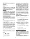
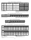
Sensor Configuration
The CO
2
sensor has preset standard voltage settings that
can be selected anytime after the sensor is powered up. See
Table 5.
Use setting 1 or 2 for Bryant equipment. See Table 5.
1. Press Clear and Mode buttons. Hold at least 5 sec-
onds until the sensor enters the Edit mode.
2. Press Mode twice. The STDSET Menu will appear.
3. Use the Up/Down button to select the preset number.
See Table 5.
4. Press Enter to lock in the selection.
5. Press Mode to exit and resume normal operation.
The custom settings of the CO
2
sensor can be changed any-
time after the sensor is energized. Follow the steps below to
change the non-standard settings:
1. Press Clear and Mode buttons. Hold at least 5 sec-
onds until the sensor enters the Edit mode.
2. Press Mode twice. The STDSET Menu will appear.
3. Use the Up/Down button to toggle to the NONSTD
menu and press Enter.
4. Use the Up/Down button to toggle through each of
the nine variables, starting with Altitude, until the
desired setting is reached.
5. Press Mode to move through the variables.
6. Press Enter to lock in the selection, then press Mode
to continue to the next variable.
Dehumidification of Fresh Air with DCV Control
Information from ASHRAE indicates that the largest humid-
ity load on any zone is the fresh air introduced. For some
applications, a device such as an energy recovery unit is
added to reduce the moisture content of the fresh air being
brought into the building when the enthalpy is high. In most
cases, the normal heating and cooling processes are more
than adequate to remove the humidity loads for most com-
mercial applications.
If normal rooftop heating and cooling operation is not ade-
quate for the outdoor humidity level, an energy recovery unit
and/or a dehumidification option should be considered.
(T
O
x
OA
)+ (T
R
x
RA
) = T
M
100 100