


Cancels: II 581B-36-6 II 581B-36-7
10/1/05
installation, start-up and
service instructions
SINGLE PACKAGE ROOFTOP
GAS HEATING/ELECTRIC COOLING UNITS
581B
Dura
Pac
Plus Series
Sizes 036-072
3 to 6 Tons
CONTENTS
Page
SAFETY CONSIDERATIONS . . . . . . . . . . . . . . . . . . . . . . . . . 1
INSTALLATION . . . . . . . . . . . . . . . . . . . . . . . . . . . . . . . . . 1-33
I. Step 1 — Provide Unit Support. . . . . . . . . . . . . . . . . 1
II. Step 2 — Field Fabricate Ductwork . . . . . . . . . . . . . 2
III. Step 3 — Determine Location of Drain Line
and External Trap. . . . . . . . . . . . . . . . . . . . . . . . . . . . 2
IV. Step 4 — Rig and Place Unit. . . . . . . . . . . . . . . . . . . 4
V. Step 5 — Install Flue Hood . . . . . . . . . . . . . . . . . . . . 4
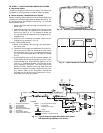
VI. Step 6 — Install Gas Piping . . . . . . . . . . . . . . . . . . . 4
VII. Step 7 — Make Electrical Connections . . . . . . . . . . 9
VIII. Step 8 — Adjust Factory-Installed Options. . . . . . 13
IX. Step 9 — Adjust Evaporator-Fan Speed . . . . . . . . 22
PRE-START-UP. . . . . . . . . . . . . . . . . . . . . . . . . . . . . . . . . . . 34
START-UP . . . . . . . . . . . . . . . . . . . . . . . . . . . . . . . . . . . . .34-37
SERVICE . . . . . . . . . . . . . . . . . . . . . . . . . . . . . . . . . . . . . .38-44
TROUBLESHOOTING. . . . . . . . . . . . . . . . . . . . . . . . . . . .45-49
INDEX . . . . . . . . . . . . . . . . . . . . . . . . . . . . . . . . . . . . . . . . . . 50
START-UP CHECKLIST . . . . . . . . . . . . . . . . . . . . . . . . . . CL-1
SAFETY CONSIDERATIONS
Installation and servicing of air-conditioning equipment can
be hazardous due to system pressure and electrical compo-
nents. Only trained and qualified service personnel should
install, repair, or service air-conditioning equipment.
Untrained personnel can perform basic maintenance func-
tions of cleaning coils and filters and replacing filters. All
other operations should be performed by trained service per-
sonnel. When working on air-conditioning equipment,
observe precautions in the literature, tags and labels
attached to the unit, and other safety precautions that may
apply.
Follow all safety codes. Wear safety glasses and work gloves.
Use quenching cloth for unbrazing operations. Have fire
extinguishers available for all brazing operations.
INSTALLATION
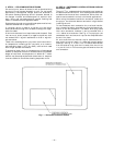
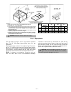
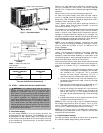
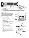
Unit is shipped in the vertical configuration. To convert to
horizontal application, remove side duct opening covers.
Using the same screws, install covers on vertical duct open-
ings with the insulation-side down. Seals around duct open-
ings must be tight. See Fig. 1.
I. STEP 1 — PROVIDE UNIT SUPPORT
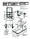
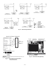
A. Roof Curb
Assemble and install accessory roof curb in accordance with
instructions shipped with curb. See Fig. 2. Install insulation,
cant strips, roofing felt, and counter flashing as shown. Duct-
work must be attached to curb. If gas is to be routed through
the curb, attach the accessory thru-the-curb service connec-
tion plate to the roof curb in accordance with the accessory
installation instructions. Connection plate must be installed
before unit is set in roof curb.
IMPORTANT: The gasketing of the unit to the roof curb is crit-
ical for a watertight seal. Install gasket supplied with the roof
curb as shown in Fig. 2. Improperly applied gasket can also
result in air or water leaks and poor unit performance.
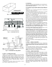
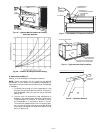
Curb should be level. This is necessary for unit drain to func-
tion properly. Unit leveling tolerances are shown in Fig. 3.
Refer to Accessory Roof Curb Installation Instructions for
additional information as required.
B. Slab Mount (Horizontal Units Only)
Provide a level concrete slab that extends a minimum of 6 in.
beyond unit cabinet. Install a gravel apron in front of con-
denser coil air inlet to prevent grass and foliage from
obstructing airflow.
NOTE: Horizontal units may be installed on a roof curb if
required.
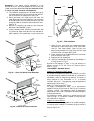
C. Alternate Unit Support
A non-combustible sleeper rail can be used in the unit curb
support area. If sleeper rails cannot be used, support the long
sides of the unit with a minimum of 3 equally spaced 4-in. x
4-in. pads on each side.
CAUTION: Ensure voltage listed on unit data plate
agrees with electrical supply provided for the unit.
WARNING: Disconnect gas piping from unit when
leak testing at pressure greater than
1
/
2
psig. Pressures
greater than
1
/
2
psig will cause gas valve damage result-
ing in hazardous condition. If gas valve is subjected to
pressure greater than
1
/
2
psig, it must be replaced before
use. When pressure testing field-supplied gas piping at
pressures of
1
/
2
psig or less, a unit connected to such
piping must be isolated by manually closing the gas
valve(s).
WARNING: Before performing service or mainte-
nance operations on unit, turn off main power switch to
unit. Electrical shock could cause personal injury.