


—9—
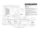
Route power and ground lines through control box end panel
or unit basepan (see Fig. 4 and 5) to connections as shown on
unit wiring diagram and Fig. 14.
Field wiring must conform to temperature limitations for
type “T” wire. All field wiring must comply with NEC and
local requirements.
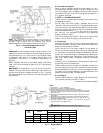
Transformer no. 1 is wired for 230-v unit. If 208/230-v unit is
to be run with 208-v power supply, the transformer must be
rewired as follows:
1. Remove cap from red (208 v) wire.
2. Remove cap from orange (230 v) spliced wire.
3. Replace orange wire with red wire.
4. Recap both wires.
IMPORTANT: BE CERTAIN UNUSED WIRES ARE
CAPPED. Failure to do so may damage the transformers.
Operating voltage to compressor must be within voltage
range indicated on unit nameplate. On 3-phase units, volt-
ages between phases must be balanced within 2%.
Unit failure as a result of operation on improper line voltage
or excessive phase imbalance constitutes abuse and may
cause damage to electrical components. Such operation
would invalidate any warranty.
B. Field Control Wiring
The unit must have a separate electrical service with a field-
supplied, waterproof, fused disconnect switch mounted at, or
within sight from, the unit. Refer to the unit rating plate for
maximum fuse/circuit breaker size and minimum circuit
amps (ampacity) for wire sizing. Be sure disconnect switch
does not obstruct unit rating plate.
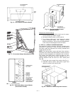
The field-supplied disconnect switchbox may be mounted on
the unit over the high-voltage inlet hole in the control corner
panel.
Connect ground lead to chassis ground connection when
using separate ground wire. The unit has a terminal block
for field power connections. Install conduit connectors in side
panel power supply knockout openings indicated in Fig. 4
and 5. Route power lines through connector to unit control
box.
Install a Bryant approved accessory thermostat assembly
according to the installation instructions included with the
accessory. Locate thermostat assembly on a solid wall in the
conditioned space to sense average temperature.
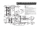
Route thermostat cable or equivalent single leads of colored
wire from subbase terminals through conduit in unit to low-
voltage connections as shown on unit label wiring diagram
and in Fig. 15.
NOTE: For wire runs up to 50 ft, use no. 18 AWG (American
Wire Gage) insulated wire (35 C minimum). For 50 to 75 ft,
use no. 16 AWG insulated wire (35 C minimum). For over
75 ft, use no. 14 AWG insulated wire (35 C Minimum).
All wire larger than no. 18 AWG cannot be directly connected
at the thermostat and will require a junction box and splice
at the thermostat.
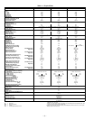
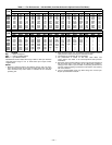
Set heat anticipator settings as follows:
The room thermostat heat anticipator must be properly
adjusted to ensure proper heating performance. Set the heat
anticipator to settings based on the table above, by using an
ammeter to determine the exact setting for stages 1 and 2.
Failure to make a proper heat anticipator adjustment may
result in improper operation, discomfort to the occupants of
the conditioned space, and inefficient energy utilization;
however, the required setting may be changed slightly to pro-
vide a greater degree of comfort for a particular installation.
Refer to Accessory Remote Control Panel instructions if
required.
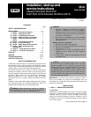
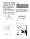
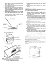
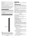
STEP 9 — MAKE OUTDOOR-AIR INLET ADJUSTMENTS
A. Manual Outdoor-Air Damper
All units (except those equipped with a factory-installed
economizer) have a manual outdoor-air damper to provide
ventilation air.
Damper can be preset to admit up to 25% outdoor air into
return-air compartment. To adjust, loosen securing screws
and move damper to desired setting. Retighten screws to
secure damper (Fig. 16).
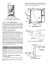
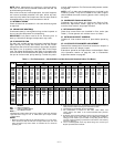
B. Optional Economizer
Economizer Motor Control Module (See Fig. 17-19)
The economizer control location is shown Fig. 17. For maxi-
mum benefit of outdoor air, set economizer motor control
module to the “D” setting (Fig. 18). The economizer motor
control module is located on the economizer motor. See
Fig. 19.
CAUTION: The correct power phasing is critical in
the operation of the scroll compressors. An incorrect
phasing will cause the compressor to rotate in the
wrong direction. This may lead to premature compres-
sor failure.
WARNING: The unit must be electrically grounded
in accordance with local codes and NEC ANSI/NFPA
70 (National Fire Protection Association).
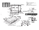
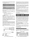
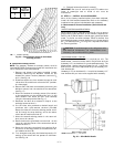
VOLTAGE W1 W2
208/230
0.98 0.44
460
0.80 0.44
NOTE:
The maximum wire size for TB1 is 2/0.
LEGEND
Fig. 14 — Field Power Wiring Connections
EQUIP —
Equipment
GND —
Ground
NEC —
National Electrical Code
TB —
Terminal Board
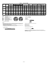
Fig. 15 — Field Control Thermostat Wiring