


—12—
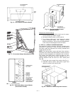
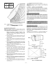
3. Secure lower filter retainer and long section of filter
support bracket to unit. See Fig. 22. Leave screws
loose on 180 and 240 units.
4. Slide baffle (sizes 180 and 240) behind lower filter
retainer and tighten screws.
5. Loosen sheet metal screws for top panel of base unit-
located above outdoor-air inlet opening, and remove
screws for hood side panels located on the sides of the
outdoor-air inlet opening.
6. Match notches in hood top panel with unit top panel
screws. Insert hood flange between top panel flange
and unit. Tighten screws.
7. Hold hood side panel flanges flat against unit, and
install screws removed in Step 5.
8. Insert outdoor-air inlet screens and spacer in channel
created by lower filter retainer and filter support
bracket.
9. Attach remaining short section of filter support
bracket.
A. Enthalpy Control Installation
NOTE: The accessory outdoor-air enthalpy sensor must be
installed BEFORE the economizer hoods are installed on the
unit or hoods will have to be removed.
1. Remove and discard the factory-installed jumper
assembly containing the 800-ohm resistor on the
economizer control module (between terminals S
R
and +). See Fig. 18.
2. Remove black wire assembly containing the 620-ohm
resistor from between economizer control module ter-
minal S
O
and the outdoor-air thermostat (OAT). Place
this wire assembly (containing the 620-ohm resistor)
between economizer control module terminals S
R
and
+, replacing the jumper removed in Step 1. See
Fig. 18.
3. Disconnect the blue wire from the OAT.
4. Remove OAT from the outside of the economizer. See
Fig. 17.
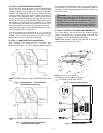
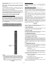
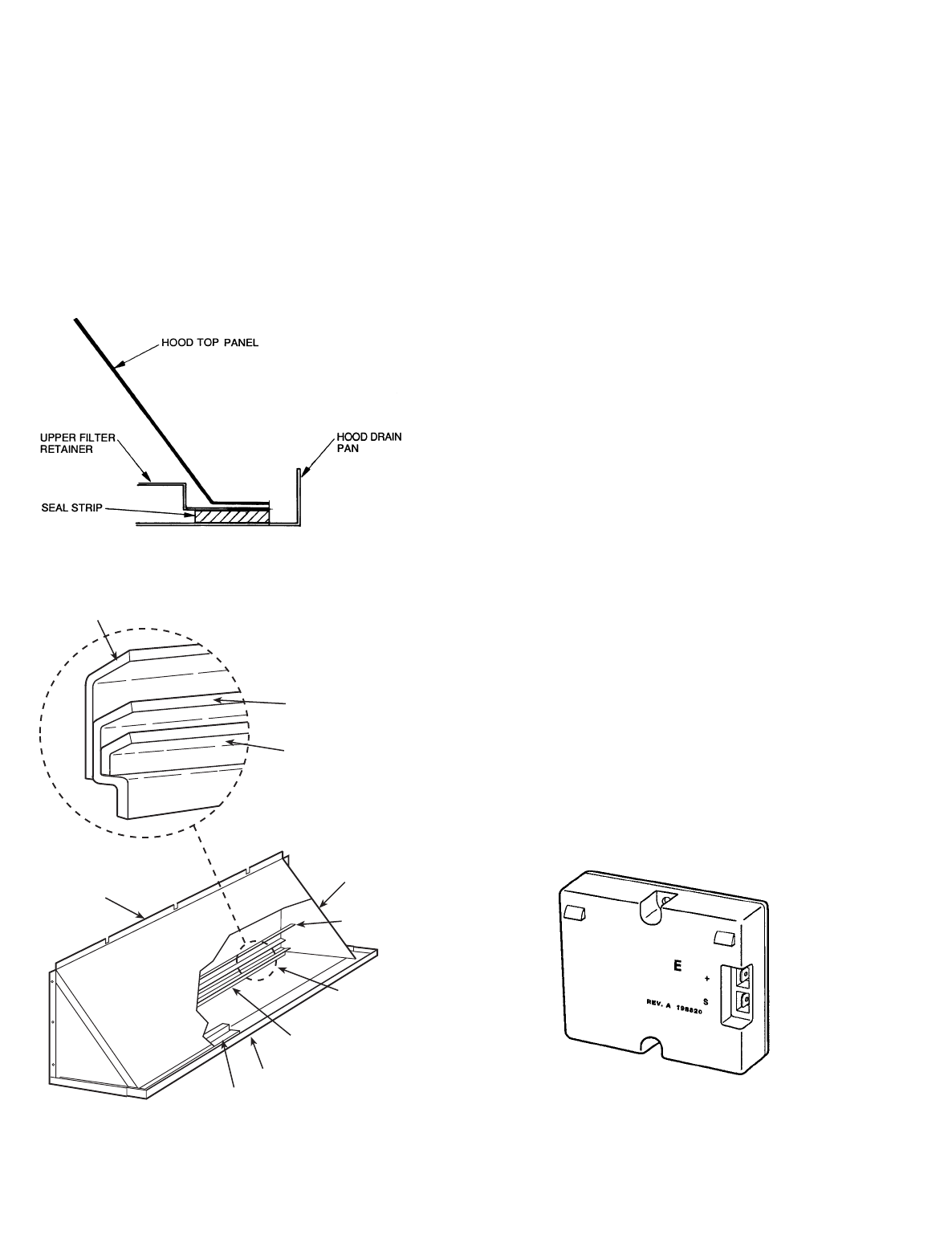
5. Mount the enthalpy sensor (Fig. 23) to the econo-
mizer on the outside of the unit (in the same location
from which the OAT was removed) using the 2 screws
provided. See Fig. 17.
6. Reconnect the blue wire removed in Step 3 to the
enthalpy sensor terminal +.
7. Cut the violet wire provided to desired length and
terminate with quick-connect terminal provided.
Route the violet wire from the enthalpy sensor termi-
nal S, through the snap bushing, and to the econo-
mizer control module terminal S
O
. See Fig. 18.
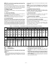
8. Set changeover set point to the desired location. See
Fig. 24.
NOTE: For maximum benefit of outdoor air, set the enthalpy
control to the “A” setting. At this setting, when the relative
humidity is 50% and the outdoor air is below 74 F, the relay
contacts on the sensor will be closed.
9. Reinstall economizer hoods if removed.
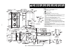
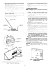
IMPORTANT: Be sure all seal strips and RTV sealant are
intact. A watertight seal to inside of unit must be
maintained.
HOOD TOP
PANEL
HOOD SIDE
PANELS (2)
BAFFLE
(180 AND
240
ONLY)
LOWER
FILTER
RETAINER
FILTER SUPPORT
BRACKET
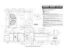
HOOD DRAIN PAN
UPPER FILTER RETAINER
BAFFLE (180 AND 240 SIZES ONLY)
LOWER FILTER
RETAINER
FILTER SUPPORT
BRACKET
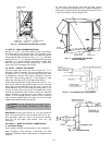
Fig. 21 — Seal Strip Location
NOTE:
The outdoor air hood comes with a baffle which is used on
sizes 180 and 240 only. Discard baffle for size 155 units.
Fig. 22 — Outdoor-Air Hood Details
Fig. 23 — Outdoor-Air and Return-Air
Enthalpy Sensor