


—24—
XIII. GAS HEAT
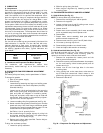
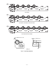
Verify gas pressures before turning on heat as follows:
1. Turn off manual gas stop.
2. Connect pressure gage to supply gas pressure tap
(see Fig. 13).
3. Connect pressure gage to manifold pressure tap on
gas valve.
4. Turn on manual gas stop and set thermostat to
HEAT position. After the unit has run for several
minutes, verify that incoming pressure is 5.5 in. wg
or greater, and that the manifold pressure is
3.3 in. wg. If manifold pressure must be adjusted,
refer to Gas Valve Adjustment section on page 29.
5. After unit has been in operation for 5 minutes, check
temperature rise across the heat exchangers. See unit
informative plate for correct rise limits of the heat
supplied. Air quantities may need to be adjusted to
bring the actual rise to within the allowable limits.
XIV. BASE UNIT OPERATION
A. Cooling, Units Without Economizer
When thermostat calls for cooling, terminals G and Y1 are
energized. The indoor (evaporator) fan contactor (IFC) and-
compressor contactor no. 1 (C1) are energized and evapora-
tor-fan motor (IFM), compressor no. 1 and condenser fan
start. The condenser-fan motors run continuously while unit
is cooling. If the thermostat calls for a second stage of cooling
by energizing Y2, compressor contactor no. 2 (C2) is ener-
gized and compressor no. 2 starts.
B. Heating, Units Without Economizer
NOTE: The 581A155-240 units have 2 stages of heat.
When the thermostat calls for heating, power is sent to W on
the IGC (integrated gas unit controller) board. An LED
(light-emitting diode) on the IGC board will be on during
normal operation. A check is made to ensure that the rollout
switch and limit switch are closed and the induced-draft
motor is running. The induced-draft motor is then energized,
and when speed is proven with the hall effect sensor on the
motor, the ignition activation period begins. The burners will
ignite within 5 seconds.
If the burners do not light, there is a 22-second delay before
another 5-second attempt. If the burners still do not light,
this sequence is repeated for 15 minutes. After the 15 min-
utes have elapsed, if the burners still have not lighted, heat-
ing is locked out. To reset the control, break 24-v power to
the thermostat.
When ignition occurs the IGC board will continue to monitor
the condition of the rollout and limit switches, the hall effect
sensor, as well as the flame sensor. If the unit is controlled
through a room thermostat set for fan auto.,45 seconds after
ignition occurs, the indoor-fan motor will be energized (and
the outdoor-air dampers will open to their minimum posi-
tion). If for some reason the overtemperature limit opens
prior to the start of the indoor fan blower, on the next
attempt, the 45-second delay will be shortened to 5 seconds
less than the time from initiation of heat to when the limit
tripped. Gas will not be interrupted to the burners and heat-
ing will continue. Once modified, the fan on delay will not
change back to 45 seconds unless power is reset to the
control.
When additional heat is required, W2 closes and initiates
power to the second stage of the main gas valve. When the
thermostat is satisfied, W1 and W2 open and the gas valve
closes, interrupting the flow of gas to the main burners. If
the call for W1 lasted less than 1 minute, the heating cycle
will not terminate until 1 minute after W1 became active. If
the unit is controlled through a room thermostat set for fan
auto., the indoor-fan motor will continue to operate for an
additional 45 seconds then stop (and the outdoor-air damp-
ers will close). If the overtemperature limit opens after the
indoor motor is stopped within 10 minutes of W1 becoming
inactive, on the next cycle the time will be extended by
15 seconds. The maximum delay is 3 minutes. Once modi-
fied, the fan off delay will not change back to 45 seconds
unless power is reset to the control.
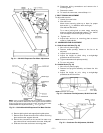
A LED indicator is provided on the IGC to monitor opera-
tion. The IGC is located by removing the side panel and
viewing the IGC through the view port located in the control
box access panel. See Fig. 28. During normal operation, the
LED is continuously on. See Table 15 for error codes.
Table 15 — IGC LED Indications
LEGEND
NOTES:
1. There is a 3-second pause between error code displays.
2. If more than one error code exists, all applicable error codes will be
displayed in numerical sequence.
3. Error codes on the IGC will be lost if power to the unit is interrupted.
C. Cooling, Units With Economizer
Upon a call for cooling, when outdoor ambient is above the
changeover control setting, the economizer damper moves to
VENT position. The compressors and evaporator and con-
denser fans energize and operate as per Cooling, Units With-
out Economizer section on this page.
Upon a first call for cooling, when outdoor ambient is below
the changeover control setting, the evaporator fan starts and
the economizer is fully open. The compressors remain off.
ERROR CODE LED INDICATION
Normal Operation
On
HardwareFailure
Off
Fan On/Off Delay
Modified
1 Flash
Limit Switch Fault
2 Flashes
Flame Sense Fault
3 Flashes
Five Consecutive Limit
Switch Faults
4 Flashes
Ignition Lockout Fault
5 Flashes
Inducer Switch Fault
6 Flashes
Rollout Switch Fault
7 Flashes
Internal Control Fault
8 Flashes
IGC —
Integrated Gas Unit Controller
LED —
Light-Emitting Diode
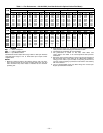
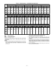
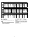
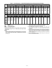
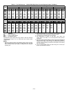
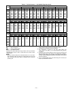
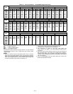
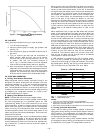
Fig. 27 — Fan Performance Using Accessory
Power Exhaust