


—28—
4. Tighten setscrews and replace rubber hubcap to pre-
vent hub from rusting to motor shaft.
5. Fill hub recess with permagum if rubber hubcap is
missing.
VII. ECONOMIZER ADJUSTMENT
See Tables 16 and 17 for checkout and outdoor air tempera-
ture simulation. Make certain the outdoor-air damper is
fully closed and the return-air damper is fully open before
completing the following steps:
1. Turn on power to the unit.
2. Turn the thermostat fan switch to the ON position.
The damper will go to the vent position.
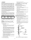
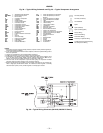
3. Adjust the vent position with the minimum damper-
position adjustment on the economizer motor control
module. See Fig. 18.
4. Set the system selector switch to COOL position and
set the cooling temperature selector to its lowest
setting.
NOTE: The Cooling mode may also be simulated by
removing the thermostat wires from terminals Y1
and Y2 and installing a jumper between terminals R
and Y1. Refer to unit label diagram for terminal
locations.
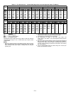
Table 16 — Economizer Checkout Procedures
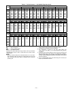
Table 17 — High and Low Outdoor-Air Simulation
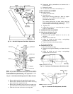
5. Set the outdoor-air thermostat (OAT), located in the
economizer section of the unit (see Fig. 17) to 75 F.
6. If the outdoor temperature is below 75 F, the econo-
mizer will control the mixed air with the mixed-air
sensor. If the outdoor air is above 75 F, place a jumper
around the contacts of the OAT.
7. Jumper terminal T to terminal T1 on the module (see
Fig. 18). The economizer will go to the full open posi-
tion. The outdoor-air damper will go to the full open
position, and the return-air damper will go to the full
closed position.
8. Adjust mechanical linkage, if necessary, for correct
positioning. If may be necessary to remove the filters
to adjust the linkage.
9. Remove the jumper from around the contacts of the
OAT if installed in Step 6. Remove the jumper from
terminals T and T1 installed in Step 7.
10. If the Cooling mode was simulated to operate the unit
in Step 4, remove the jumper and reconnect the ther-
mostat wires to terminals Y1 and Y2.
VIII. POWER FAILURE
Dampers have a spring return. In event of power failure,
dampers will return to fully closed position until power is
restored. Do not manually operate damper motor.
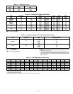
IX. REFRIGERANT CHARGE
Amount of refrigerant charge is listed on unit nameplate and
in Table 1. Refer to Carrier GTAC II; Module 5; Charging,
Recovery, Recycling, and Reclamation section for charging
methods and procedures. Unit panels must be in place when
unit is operating during charging procedure.
NOTE: Do not use recycled refrigerant as it may contain
contaminants.
A. No Charge
Use standard evacuating techniques. After evacuating sys-
tem, weigh in the specified amount of refrigerant (refer to
Table 1).
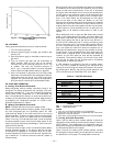
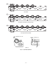
B. Low Charge Cooling
Using appropriate cooling charging chart (see Fig. 35), add
or remove refrigerant until conditions of the chart are met.
Note that charging chart is different from those normally
used. An accurate pressure gage and temperature-sensing
device is required. Charging is accomplished by ensuring the
proper amount of liquid sub-cooling. Measure liquid line
pressure at the liquid line service valve using pressure gage.
Connect temperature sensing device to the liquid line near
the liquid line service valve and insulate it so that outdoor
ambient temperature does not affect reading.
C. To Use the Cooling Charging Chart
Use the above temperature and pressure readings, and find
the intersection point on the cooling charging chart. If inter-
section point on chart is above line, add refrigerant. If inter-
section point on chart is below line, carefully recover some of
the charge. Recheck suction pressure as charge is adjusted.
NOTE: Indoor-air CFM must be within normal operating
range of unit. All outdoor fans must be operating.
The TXV (thermostatic expansion valve) is set to maintain
between 15 and 20 degrees of superheat at the compressors.
The valves are factory set and should not require
re-adjustment.
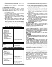
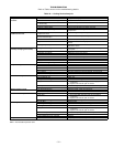
TEST PROCEDURE RESULTS
A. Disconnect power at
TR and TR1.
Disconnect jumper
between P and
P1. See Fig. 18.
B. Jumper TR to 1.
C. Jumper T1 to T.
D. Disconnect outdoor-air
thermostat connections
from S
O
and +.
Factory-installed
800 ohm resistor
should remain connected
to S
R
and +.
E. Reconnect power to
terminals TR and TR1.
1. LED (light-emitting diode)
should be off.
2. Motor is in closed position.
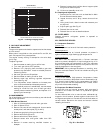
TEST PROCEDURE RESULTS
Disconnect factory-installed
resistor from terminals
S
R
and +.
1. LED should be on.
2. Motor drives toward open.
TEST PROCEDURE RESULTS
A. Reconnect factory-installed
800 ohm resistor
between terminals
SR and +.
B. Connect 1200 ohm
checkout resistor between
terminals SO and +.
C. Turn set point potentiometer
to position A.
Low outdoor-air test results:
1. LED (light-emitting
diode)should be on.
2. Motor drives toward open.
D. Turn set point potentiometer
to position D.
E. Disconnect 1200 ohm
checkout resistor.
High outdoor-air test results:
1. LED should be off.
2. Motor drives toward closed.