


—29—
X. GAS VALVE ADJUSTMENT
A. Natural Gas
The gas valve opens and closes in response to the thermostat
or limit control.
When power is supplied to valve terminals D1 and C2, the
main valve opens to its preset position.
The regular factory setting is stamped on the valve body
(3.3 in. wg).
To adjust regulator:
1. Set thermostat at setting for no call for heat.
2. Turn main gas valve to OFF position.
3. Remove
1
/
8
-in. pipe plug from manifold or gas valve
pressure tap connection. Install a suitable pressure-
measuring device.
4. Set main gas valve to ON position.
5. Set thermostat at setting to call for heat.
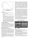
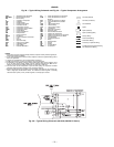
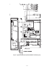
6. Remove screw cap covering regulator adjustment
screw (See Fig. 36).
7. Turn adjustment screw clockwise to increase pres-
sure or counterclockwise to decrease pressure.
8. Once desired pressure is established, set thermostat
setting for no call for heat, turn off main gas valve,
remove pressure-measuring device, and replace
1
/
8
-in.
pipe plug and screw cap.
XI. MAIN BURNERS
For all applications, main burners are factory set and should
require no adjustment.
A. Main Burner Removal
1. Shut off (field-supplied) manual main gas valve.
2. Shut off power to unit.
3. Remove unit control box access panel, burner section
access panel, and center post (Fig. 4 and 5).
4. Disconnect gas piping from gas valve inlet.
5. Remove wires from gas valve.
6. Remove wires from rollout switch.
7. Remove sensor wire and ignitor cable from IGC
board.
8. Remove 2 screws securing manifold bracket to
basepan.
9. Remove 2 screws that hold the burner support plate
flange to the vestibule plate.
10. Lift burner assembly out of unit.
B. Cleaning and Adjustment
1. Remove burner rack from unit as described in Main
Burner Removal section above.
2. Inspect burners, and if dirty, remove burners from
rack.
3. Using a soft brush, clean burners and crossover port
as required.
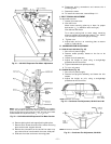
4. Adjust spark gap. See Fig. 37.
5. Reinstall burners on rack.
6. Reinstall burner rack as described above.
XII. FILTER DRIER
Replace whenever refrigerant system is exposed to
atmosphere.
XIII. PROTECTIVE DEVICES
A. Compressor Protection
Overcurrent
Each compressor has internal line break motor protection.
Overtemperature
Each compressor has an internal protector to protect it
against excessively high discharge gas temperatures.
Crankcase Heater
The 581A units are equipped with a 70-watt crankcase
heater to prevent absorption of liquid refrigerant by oil in
the crankcase when the compressor is idle. The crankcase
heater is energized whenever there is main power to the unit
and the compressor is not energized.
IMPORTANT: After prolonged shutdown or servicing, ener-
gize the crankcase heaters for 24 hours before starting the
compressors.
Compressor Lockout
If any of the safeties (high-pressure, low-pressure, freeze
protection thermostat, compressor internal thermostat) trip,
or if there is loss of power to the compressors, the cooling
lockout (CLO) will lock the compressors off. To reset, manu-
ally move the thermostat setting.
B. Evaporator Fan Motor Protection
On size 155 units, an internal protector with auto-reset is
included in the indoor fan motor as a protection against
overcurrent.
On size 180 and 240 units, a manual reset, calibrated trip,
magnetic circuit breaker protects against overcurrent. Do
not bypass connections or increase the size of the breaker to
correct trouble. Determine the cause and correct it before
resetting the breaker.
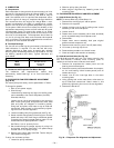
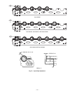
Fig. 35 — Cooling Charging Chart
50
40
100
150
200
250
300
350
400
60
80
100
120
140
ALL OUTDOOR FANS MUST BE OPERATING
LIQUID PRESSURE AT LIQUID VALVE (PSIG)
LIQUID TEMPERATURE AT LIQUID VALVE (DEG F)
BOTH CIRCUITS
REDUCE CHARGE IF BELOW CURVE
ADD CHARGE IF ABOVE CURVE
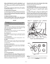
Fig. 36 — Gas Valve