


—14—
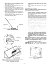
Sensor Assembly — Install the sensor assembly in the loca-
tion shown in Fig. 26.
Motor Mount — To ensure proper fan height, replace the
existing motor mount with the new motor mount provided
with accessory.
Transformer (460-v Units Only) — On 460 volt units, a trans-
former is required. The transformer is provided with the
accessory and must be field-installed.
Motormaster® I Control — Recommended mounting location
is on the inside of the panel to the left of the control box. The
control should be mounted on the inside of the panel, verti-
cally, with leads protruding from bottom of extrusion.
B. Motormaster III Control Installation (581A240)
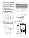
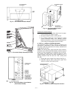
Install Field-Fabricated Wind Baffles
Wind baffles must be field-fabricated for all units to ensure
proper cooling cycle operation at low ambient temperatures.
See Fig. 25 for baffle details. Use 20-gage, galvanized sheet
metal, or similar corrosion-resistant metal for baffles. Use
field-supplied screws to attach baffles to unit. Screws should
be
1
/
4
-in. diameter and
5
/
8
-in. long. Drill required screw holes
for mounting baffles.
Replace Outdoor Motor
Replace outdoor-fan motor no. 1 with motor included in
accessory kit. Existing motor is not Motormaster III
compatible.
Install Motormaster III Controls
Only one Motormaster III control is required per unit.
Sensor — Install the sensor for thermistor input control in
the location shown in Fig. 26. Connect sensor leads to the
purple and grey control signal leads on the Motormaster III
control.
Signal Selection Switch — Remove the cover of the Motor-
master III control. Set the switch to accept the thermistor
sensor input signal. Set the frequency to match the unit
power supply (60 Hz).
Motormaster III Control — Recommended mounting location
is beneath the control box, mounted to the partition that sep-
arates the control box section from the indoor section.
NOTE: If unit power is supplied through the roof curb and
basepan of the unit, mount the Motormaster III control on
the corner post adjacent to the conduit running from the
basepan to the bottom of the control box.
START-UP
Use the following information and Start-Up Checklist on
page CL-1 to check out unit PRIOR to start-up.
I. UNIT PREPARATION
Check that unit has been installed in accordance with these
installation instructions and all applicable codes.
II. SERVICE VALVES
Ensure that the liquid line service valve is open. Damage to
the compressor could result if it is left closed.
III. COMPRESSOR MOUNTING
Compressors are internally spring mounted. Do not loosen or
remove compressor holddown bolts.
IV. REFRIGERANT SERVICE PORTS
Each refrigerant system has a total of 3 Schrader-type ser-
vice gage ports. One port is located on the suction line, one
on the compressor discharge line, and one on the liquid line.
In addition Schrader-type valves are located underneath the
low-pressure switches. Be sure that caps on the ports are
tight.
V. COMPRESSOR ROTATION
It is important to be certain the compressors are rotating in
the proper direction. To determine whether or not compres-
sors are rotating in the proper direction:
1. Connect service gages to suction and discharge pres-
sure fittings.
2. Energize the compressor.
3. The suction pressure should drop and the discharge
pressure should rise, as is normal on any start-up.
If the suction pressure does not drop and the discharge pres-
sure does not rise to normal levels:
1. Note that the evaporator fan is probably also rotating
in the wrong direction.
2. Turn off power to the unit.
3. Reverse any two of the incoming power leads.
4. Turn on power to the compressor.
The suction and discharge pressure levels should now move
to their normal start-up levels.
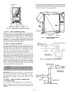
CAUTION: To avoid damage to the refrigerant
coils and electrical components, use recommended
screw sizes only. Use care when drilling holes.
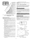
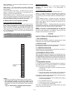
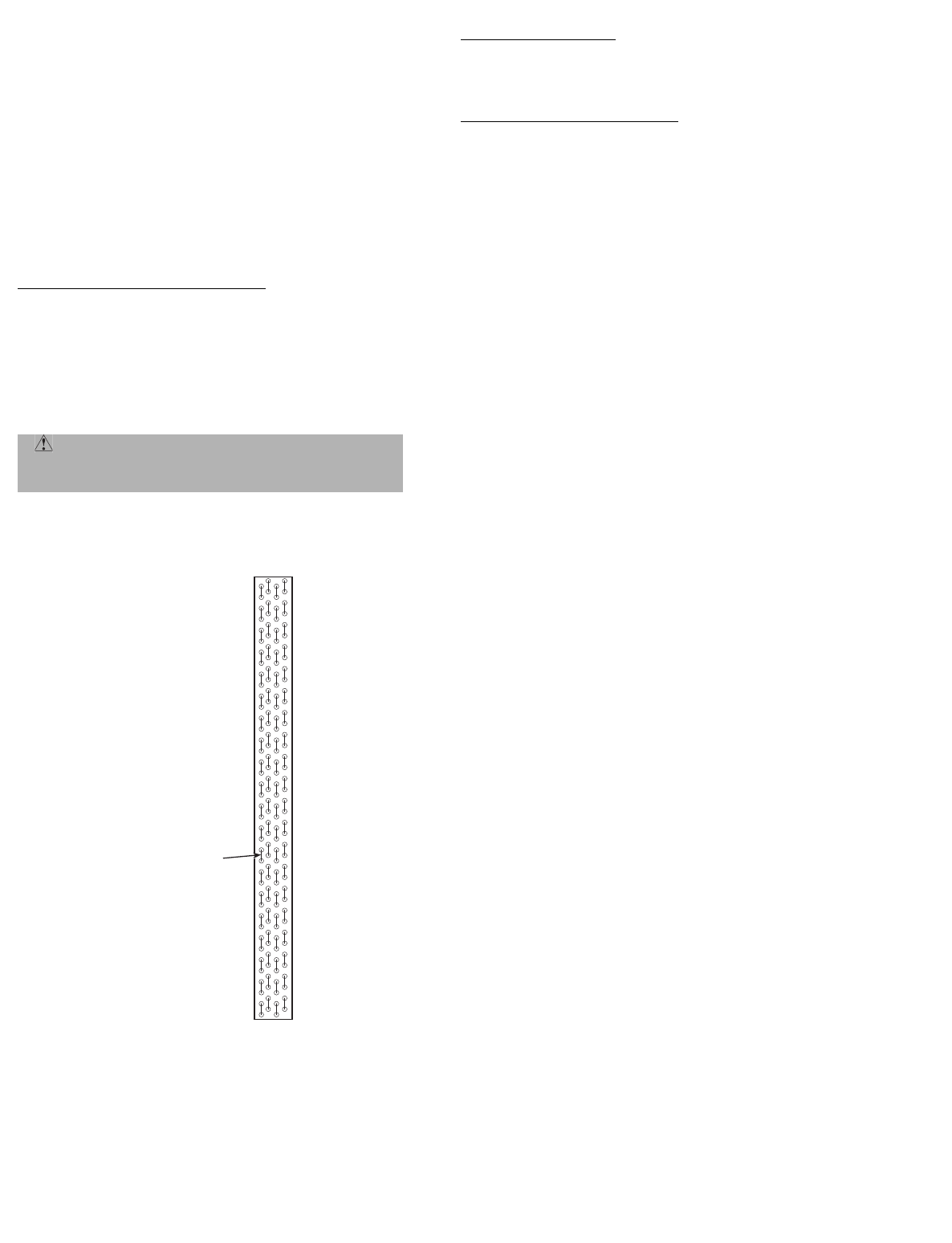
MOTORMASTER
SENSOR
LOCATION
HAIRPIN END
NOTES:
1. All sensors are located on the eighth hairpin up from the bottom.
2. Field installed tubing insulation is required to be installed over the
TXV (thermostatic expansion valve) bulb and capillary tube for
proper operation at low ambients. Tubing insulation is only required
on the portion of suction line located between indoor and outdoor
section.
Fig. 26 — Motormaster I and Motormaster III Sensor
Locations