


—6—
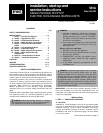
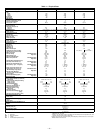
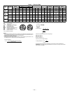
Table 1 — Physical Data
LEGEND
*Evaporator coil fin material/condenser coil fin material.
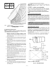
†Weight of 14-in. roof curb.
**Circuit 1 uses the lower portion of condenser coil and lower portion of evaporator coils, and
Circuit 2 uses the upper portion of both coils.
††Pulley has 6 turns. Due to belt and pulley, moveable pulley cannot be set to 0 to 1 turns open.
llRollout switch is manual reset.
UNIT 581A 155 180 240
NOMINAL CAPACITY (tons)
12 15 20
OPERATING WEIGHT (lb)
Unit
Al/Al*
1725 1800 1900
Al/Cu*
1875 1950 2050
Cu/Cu*
2005 2080 2180
Economizer
110 110 110
Roof Curb†
200 200 200
COMPRESSOR
Quantity
222
Number of Refrigerant Circuits
222
Crankcase Heater Watts
70 70 70
Oil (oz) (Ckt 1, Ckt 2)
60,66 85,60 110,110
REFRIGERANT TYPE
R-22
Expansion Device
TXV
Operating Charge (lb oz)
Circuit 1**
20.7 19.5 18.5
Circuit 2
11.9 13.45 13.3
CONDENSER COIL
Cross-Hatched
3
/
8
-in. Copper Tubes, Aluminum Lanced, Aluminum Pre-Coated, or Copper Plate Fins
Rows...Fins/in.
4...15 4...15 4...15
Total Face Area (sq ft)
21.7 21.7 21.7
CONDENSER FAN
Propeller Type
Nominal Cfm
10,500 10,500 14,200
Quantity...Diameter (in.)
3...22 3...22 2...30
Motor Hp...Rpm
1
/
2
...1050
1
/
2
...1050 1...1075
Watts Input (Total)
1100 1100 3400
EVAPORATOR COIL
Cross-Hatched
3
/
8
-in. Copper Tubes, Aluminum Lanced or Copper Plate Fins, Face Split
Rows...Fins/in.
4...15 4...15 4...15
Total Face Area (sq ft)
17.5 17.5 17.5
EVAPORATOR FAN
Centrifugal Type
Quantity...Size (in.)
2...10 X 10 2...12 x 12 2...12 x 12
Type Drive
Belt Belt Belt
Nominal Cfm
5200 6000 8000
Std Motor Hp
2.9 5 7.5
Opt Motor Hp
3.7
Motor Nominal Rpm
1725 1745 1745
Std Maximum Continuous Bhp
3.13 6.13 9.47 (208 v)
10.33
(230 and 460 v)
Opt Maximum Continuous Bhp
4.38
Motor Frame Size
56H 184T 213T
Fan Rpm Range Low-Medium Static
834-1064 873-1021 1002-1151
High Static
1161-1426 1025-1200 1193-1369
Motor Bearing Type
Ball Ball Ball
Maximum Allowable Rpm
1550 1550 1550
Motor Pulley Pitch Dia. Low-Medium Static
3.1/4.1 4.9/5.9 5.4/6.6
High Static
3.7/4.7 4.9/5.9 5.4/6.6
Nominal Motor Shaft Diameter (in.)
7
/
8
1
1
/
8
1
3
/
8
Fan Pulley Pitch Diameter (in.) Low-Medium Static
6.0 9.4 9.4
High Static
5.2 8.0 7.9
Nominal Fan Shaft Diameter (in.)
1
3
/
16
1
7
/
16
1
7
/
16
Belt, Quantity...Type... Length (in.) Low-Medium Static
1...BX...42 1...BX...50 1...BX...54
High Static
1...BX...42 1...BX...48 1...BX...50
Pulley Center Line Distance (in.)
13.5-15.5 13.3-14.8 14.6-15.4
Speed Change per Full Turn of
Movable Pulley Flange (Rpm)
Low-Medium Static
58 37 37
High Static
67 44 44
Movable Pulley Maximum
Full Turns From Closed Position
4†† 4†† 4††
Factory Speed
3.5 3.5 3.5
Factory Speed Setting (Rpm) Low-Medium Static
978 965 1095
High Static
1327 1134 1303
FURNACE SECTION
Rollout Switch Cutout Temp (F) ll
190 190 190
Burner Orifice Diameter (in...drill size)
Natural Gas
0.1285...30/ 0.136...29 0.1285...30/ 0.136...29 0.1285...30/ 0.136...29
Thermostat Heat Anticipator Setting
Stage 1 (amps)
0.98 0.8 0.98 0.8 0.98 0.8
Stage 2 (amps)
0.44 0.44 0.44 0.44 0.44 0.44
GasInput(Btuh)Stage1
172,000/230,000 206,000/275,000 206,000/275,000
Stage 2
225,000/300,000 270,000/360,000 270,000/360,000
Efficiency (Steady State) (%)
81 81 81
Temperature Rise Range
15-45/30-60 15-45/20-50 15-45/20-50
Manifold Pressure (in. wg)
Natural Gas
3.3 3.3 3.3
Gas Valve Quantity
11 1
GasValvePressureRange(in.wg)
5.5-13.5 5.5-13.5 5.5-13.5
(psig)
.235-.487 .235-.487 .235-.487
Field Gas Connection Size (in.-FPT)
3
/
4
3
/
4
3
/
4
HIGH-PRESSURE SWITCH (psig)
Cutout
426
Reset (Auto.)
320
LOW-PRESSURE SWITCH (psig)
Cutout
27
Reset (Auto.)
44
FREEZE PROTECTION THERMOSTAT (F)
Opens
30 ± 5
Closes
45 ± 5
OUTDOOR-AIR INLET SCREENS
Cleanable
Quantity...Size (in.)
2...20 x 25 x 1
1...20 x 20 x 1
RETURN-AIR FILTERS
Throwaway
Quantity...Size (in.)
4...20 x 20 x 2
4...16 x 20 x 2
Al —
Aluminum
Bhp —
Brake Horsepower
Cu —
Copper
TXV —
Thermostatic Expansion Valve