


—8—
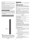
VI. STEP 6 — TRAP CONDENSATE DRAIN
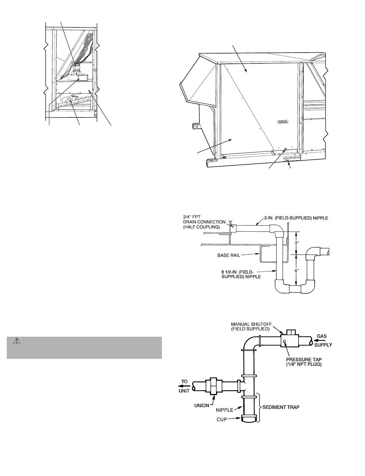
See Fig. 4, 5, and 11 fore drain location. Plug is provided in
drain hole and must be removed when unit is operating. One
3
/
4
in. half coupling is provided inside unit evaporator section
for condensate drain connection. An 8
1
/
2
in. x
3
/
4
in. diameter
nipple and a 2 in. x
3
/
4
in. diameter pipe nipple are coupled to
standard
3
/
4
in. diameter elbow to provide a straight path
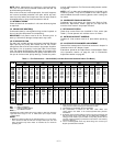
down through holes in unit base rails (see Fig. 11 and 12). A
trap at least 4 inches deep must be used.
VII. STEP 7 — INSTALL GAS PIPING
The gas supply pipe enters the unit through the 1
1
/
2
in.
diameter knockout provided. The gas connection to the unit
is made to the
3
/
4
in. FPT gas inlet on the gas manifold. Unit
is equipped for use with natural gas. Installation must con-
form with local building codes or, in the absence of local
codes, with the National Fuel Gas code, ANSI Z223.1.
Install field-supplied manual gas shutoff valve with a
1
/
8
in.
NPT pressure tap for test gage connection at unit. Field gas
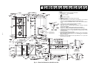
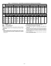
piping must include sediment trap and union. See Fig. 13.
Install sediment trap in riser leading to heating section. This
drip leg functions as a trap for dirt and condensate. Install
trap where condensate cannot freeze. Install this sediment
trap by connecting a piping tee to riser leading to heating
section, so that straight-through section of tee is vertical.
Then, connect capped nipple into lower end of tee. Extend
capped nipple below level of gas controls.
IMPORTANT: Natural gas pressure at unit gas connection
must not be less than 5.5 in. wg or greater than 13.5 in. wg.
Size gas-supply piping for 0.5-in. wg maximum pressure
drop. Do not use supply pipe smaller than unit gas
connection.
VIII. STEP 8 — MAKE ELECTRICAL CONNECTIONS
A. Field Power Supply
Unit is factory wired for voltage shown on unit nameplate.
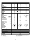
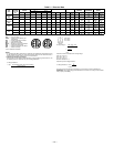
When installing units, provide a disconnect per NEC
(National Electrical Code) requirements of adequate size
(Table 2).
All field wiring must comply with NEC and local require-
ments. Insulate low-voltage wires for highest voltage con-
tained within conduit when low-voltage control wires are run
in the same conduit as high-voltage wires.
WARNING: Do not pressure test gas supply while
connected to unit. Always disconnect union before
servicing.
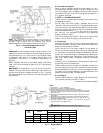
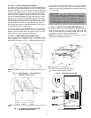
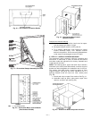
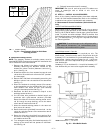
INDUCED DRAFT
MOTOR
MAIN BURNER
SECTION
COMBUSTION
FAN HOUSING
HEAT EXCHANGER
SECTION
Fig. 10 — Combustion Fan Housing Location
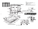
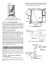
3/4" FPT DRAIN
CONNECTION
1-3/8"
DRAIN HOLE
INDOOR MOTOR ACCESS
FILTER
ACCESS
Fig. 11 — Condensate Drain Details
(581A155 Shown)
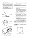
Fig. 12 — Condensate Drain Piping Details
Fig. 13 — Field Gas Piping