


—25—
Upon a second-stage call for cooling, compressor no. 1 is
energized and mechanical cooling is integrated with econo-
mizer cooling. If the outdoor-air temperature drops below
50 F, a cooling lockout switch prevents the compressors from
running.
When supply-air temperature drops below a fixed set point,
the economizer damper modulates to maintain the tempera-
ture at the fixed set point.
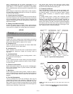
D. Freeze Protection Thermostats
A freeze protection thermostat is located on the top and bot-
tom of the evaporator coil. It detects frost build-up and locks
out the compressors, allowing the coil to clear. Once frost has
melted, the compressors can be reenergized by resetting the
compressor lockout.
E. Heating, Units With Economizer
Outdoor-air damper stays at VENT position while evapora-
tor fan is operating. Refer to Heating, Units without Econo-
mizer section on page 24 for heating sequence of operation.
SERVICE
I. CLEANING
Inspect unit interior at beginning of each heating and cooling
season and as operating conditions require. Remove unit top
panel and/or side panels for access to unit interior.
A. Evaporator Coil
Clean as required with commercial coil cleaner. Wash both
sides of coil and flush with clean water.
B. Condenser Coil
Clean condenser coil annually and as required by location
and outdoor-air conditions. Inspect coil monthly; clean as
required.
C. Condensate Drain
Check and clean each year at start of cooling season. In win-
ter, keep drains and traps dry.
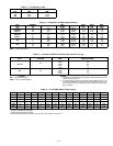
D. Filters
Clean or replace at start of each heating and cooling season,
or more often if operating conditions require. Refer to Table 1
for type and size.
E. Outdoor-Air Inlet Screens
Clean screens with steam or hot water and a mild detergent.
Do not use throwaway filters in place of screens. See Table 1
for quantity and size.
F. Main Burner
At the beginning of each heating season, inspect for deterio-
ration or blockage due to corrosion or other causes. Observe
the main burner flames. Refer to Main Burners section on
page 29.
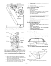
G. Flue Gas Passageways
The flue collector box and heat exchanger cells may be
inspected by removing heat exchanger access panel (Fig. 4
and 5), flue box cover, and main burner assembly (Fig. 28).
Refer to Main Burners section on page 29 for burner removal
sequence. If cleaning is required, remove heat exchanger baf-
fles and clean tubes with a wire brush.
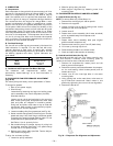
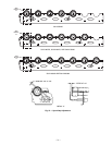
Use caution with ceramic heat exchanger baffles. When
installing retaining clip, be sure the center leg of the clip
extends inward toward baffle. See Fig. 29.
H. Combustion-Air Blower
Clean periodically to assure proper airflow and heating effi-
ciency. Inspect blower wheel every fall and periodically dur-
ing heating season. For the first heating season, inspect
blower wheel bi-monthly to determine proper cleaning
frequency.
To inspect blower wheel, remove heat exchanger access
panel. Shine a flashlight into opening to inspect wheel. If
cleaning is required, remove motor and wheel assembly by
removing screws holding motor mounting plate to top of com-
bustion fan housing (Fig. 28). The motor and wheel assembly
will slide up and out of the fan housing. Remove the blower
wheel from the motor shaft and clean with a detergent or sol-
vent. Replace motor and wheel assembly.
WARNING: Before performing service or mainte-
nance operations on unit, turn off main power switch
to unit. Electrical shock could cause personal injury.
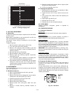
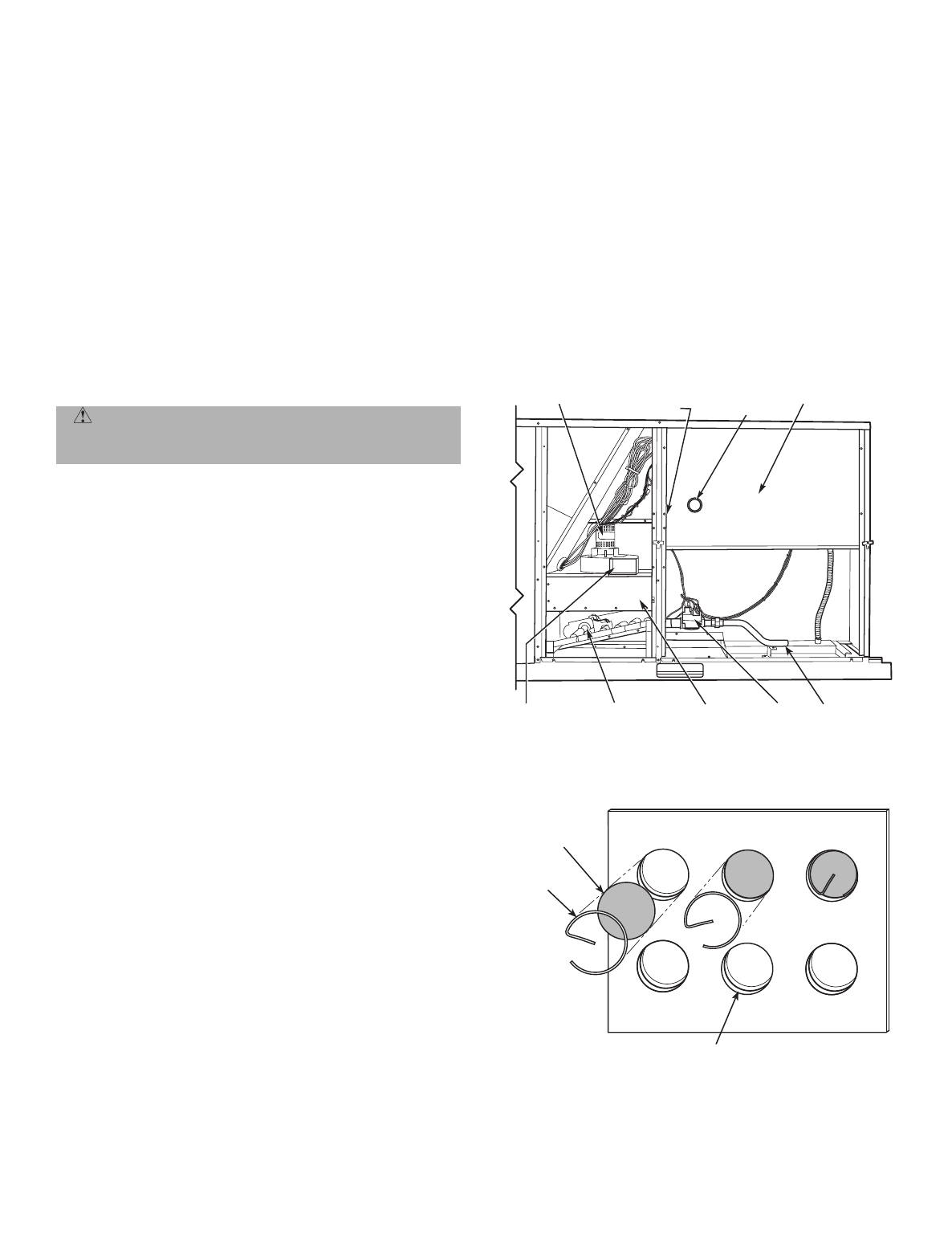
INDUCED DRAFT
MOTOR
FLUE BOX
COVER
MAIN BURNER
SECTION
MAIN GAS
VALVE
COMBUSTION
FAN HOUSING
INTEGRATED GAS
UNIT CONTROLLER
(HIDDEN)
CONTROL BOX
ACCESS PANEL
IGC LED
VIEW
PORT
FIELD GAS
CONNECTION
CERAMIC
BAFFLE
CLIP
HEAT EXCHANGER
TUBES
Fig. 28 — Typical Gas Heating Section
NOTE:
One baffle and clip will be in each upper tube of the heat
exchanger.
Fig. 29 — Removing Heat Exchanger Ceramic Baffles
and Clips