


—32—
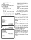
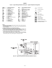
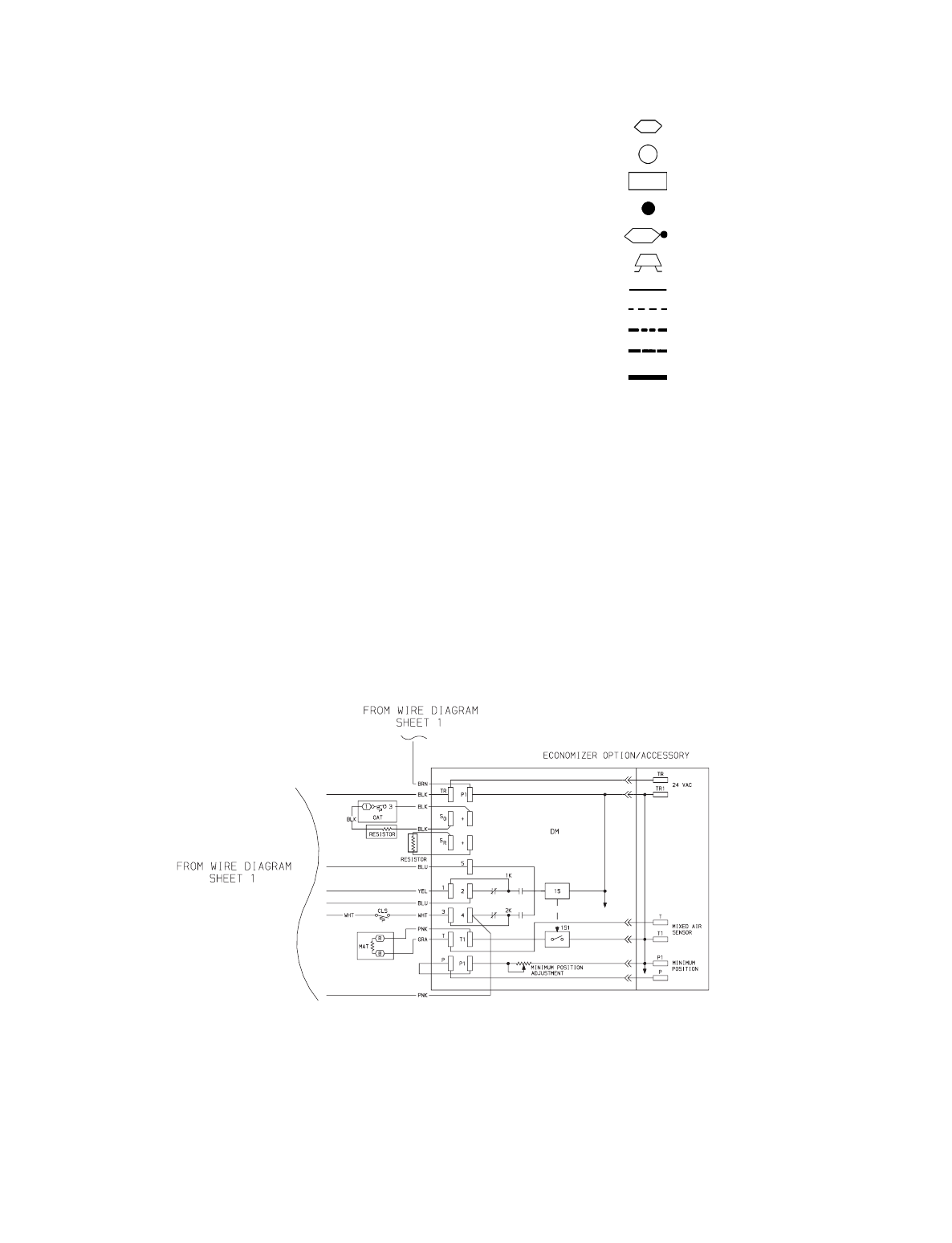
LEGEND
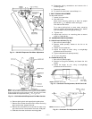
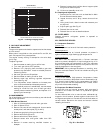
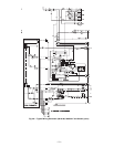
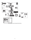
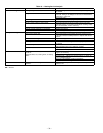
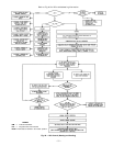
Fig. 38 — Typical Wiring Schematic and Fig. 39 — Typical Component Arrangement
AHA —
Adjustable Heat Anticipator
BKR W/AT —
Breaks with Amp Turns
BR —
Burner Relay
C—
Contactor, Compressor
CAP —
Capacitor
CB —
Circuit Breaker
CC —
Cooling Compensator
CH —
Crankcase Heater
CLO —
Compressor Lockout
CLS —
Compressor Lockout Switch
COMP —
Compressor Motor
CR —
Control Relay
CT —
Current Transformer
DM —
Damper Motor
DU —
Dummy Terminal
EQUIP —
Equipment
FPT —
Freeze Protection Thermostat
FU —
Fuse
GND —
Ground
GVR —
Gas Valve Relay
HPS —
High-Pressure Switch
HS —
Hall Effect Sensor
HV —
High Voltage
IDM —
Induced-Draft Motor
IFC —
Indoor (Evaporator) Fan Contactor
IFCB —
Indoor (Evaporator) Fan Circuit
Breaker
IFM —
Indoor (Evaporator) Fan Motor
IGC —
Integrated Gas Unit Controller
L—
Light
LED —
Light-Emitting Diode
LOR —
Lockout Relay
LPS —
Low-Pressure Switch
LS —
Limit Switch
MAT —
Mixed-Air Thermostat
MGV —
Main Gas Valve
NEC —
National Electrical Code
OAT —
Outdoor-Air Thermostat
OFC —
Outdoor (Condenser) Fan Contactor
OFM —
Outdoor (Condenser) Fan Motor
PL —
Plug Assembly
QT —
Quadruple Terminal
R—
Relay
RS —
Rollout Switch
SN —
Sensor
SW —
Switch
TB —
Terminal Block
TRAN —
Transformer
Terminal (Marked)
Terminal (Unmarked)
Terminal Block
Splice
Splice (Marked)
Splice (Field Supplied)
Factory Wiring
Field Control Wiring
Field Power Wiring
Accessory or Optional Wiring
To Indicate Common Potential Only,
Not To Represent Wiring
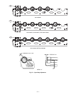
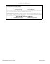
NOTES:
1. Compressor and fan motors thermally protected; 3-phase motors protected against pri-
mary single-phasing conditions.
2. If any of the original wire furnished must be replaced, it must be replaced with type 90 C
wire or its equivalent.
3. Jumpers are omitted when unit is equipped with economizer.
4. IFCB must trip amps is equal to or less than 140% full load amps.
5. On 208/230-v unit, TRAN1 is factory wired to ORN lead for 230-v power supply. If unit is
to run on 208-v power supply, TRAN1 must be rewired. Disconnect the BLK wire on
TRAN1 and connect wire to 208-v RED wire. Insulate 230-v ORN wire.
6. The CLO locks out the compressor to prevent short cycling on compressor overload
and safety devices. Before replacing CLO, check these devices.
7. Number(s) indicates the line location of used contacts. A bracket over (2) numbers sig-
nifies a single-pole, double-throw contact. An underlined number signifies a normally
closed contact. A plain (no line) number signifies a normally open conta
ct.
Fig. 38 — Typical Wiring Schematic (581A180, 208/230 V Shown)