


—7—
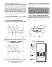
III. STEP 3 — FIELD FABRICATE DUCTWORK
On vertical units, secure all ducts to roof curb and building
structure. Do not connect ductwork to unit. Use flexible duct
connectors between unit and ducts as required. Adequately
insulate and weatherproof all ductwork located outdoors,
joints, and roof openings with counter flashing and mastic in
accordance with applicable codes. Insulate ducts passing
through unconditioned space, and use vapor barrier in accor-
dance with the latest issue of SMACNA (Sheet Metal and Air
Conditioning Contractors National Association) and ACCA
(Air Conditioning Contractors of America) minimum instal-
lation standards for heating and air conditioning systems.
Ducts passing through an unconditioned space must be insu-
lated and covered with a vapor barrier.
A minimum clearance to combustibles of 1 in. for the first
24 in. of ductwork is required for all units with electric heat.
Cabinet return-air static shall not exceed –0.35 in. wg with
economizer or –0.45 in. wg without economizer.
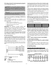
IV. STEP 4 — MAKE UNIT DUCT CONNECTIONS
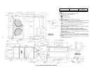
Unit is shipped for thru-the-bottom duct connections. Duct-
work openings are shown in Fig. 1, 4, and 5. Duct
connections are shown in Fig. 6. Field-fabricated concentric
ductwork may be connected as shown in Fig. 7 and 8. Attach
all ductwork to roof curb and roof curb basepans. Refer to
installation instructions shipped with accessory roof curb for
more information.
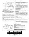
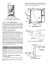
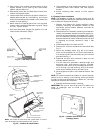
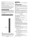
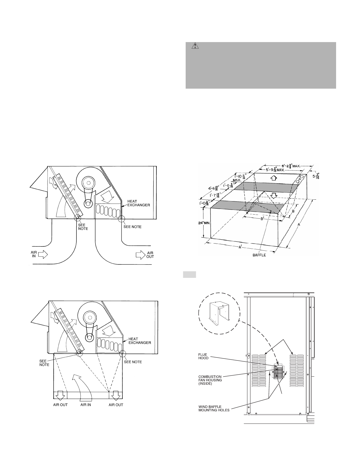
V. STEP 5 — INSTALL FLUE HOOD AND WIND BAFFLE
Flue hood, screen, and wind baffle are shipped secured
under main control box. To install, secure flue hood and
screen to access panel with screws provided. See Fig. 9. The
wind baffle is then installed over the flue hood.
NOTE: When properly installed, flue hood will line up with
combustion fan housing. See Fig. 10.
WARNING: For vertical supply and return units,
tools or parts could drop into ductwork and cause an
injury. Install a 90 degree turn in the return ductwork
between the unit and the conditioned space. If a
90 degree elbow cannot be installed, then a grille of
sufficient strength and density should be installed to
prevent objects from falling into the conditioned space.
WIND
BAFFLE
FLUE
SCREEN
INLET
LOUVERS
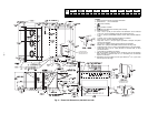
NOTE:
Do not drill in this area; damage to basepan may result in water
leak.
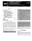
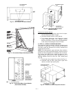
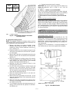
Fig. 6 — Air Distribution — Thru-the-Bottom
(581A180, 240 Unit Shown)
NOTE:
Dimensions A, A’, B and
B’ are obtained from field-supplied ceiling diffuser.
Shaded areas indicate block-off pans.
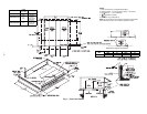
Fig. 8 — Concentric Duct Details
NOTE:
Do not drill in this area; damage to basepan may result in water
leak.
Fig. 7 — Concentric Duct Air Distribution
(581A180, 240 Unit Shown)
Fig. 9 — Flue Hood Location