


—3—
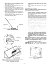
IMPORTANT:
Curb or adapter roof curb must be level. This is
necessary to permit unit drain to function properly. Unit lev-
eling tolerance is ±
1
/
16
in. per linear ft in any direction. Refer
to Accessory Roof Curb or Horizontal Supply Roof Curb
Installation Instructions for additional information as
required.
When accessory roof curb or horizontal supply roof curb is
used, unit may be installed on class A, B, or C roof covering
material.
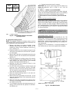
IMPORTANT:
The gasketing of the unit to the roof curb or
adapter roof curb is critical for a watertight seal. Install gas-
ket with the roof curb or adapter as shown in Fig. 1. Improp-
erly applied gasket can also result in air leaks and poor unit
performance.
B. Alternate Unit Support
When a curb or adapter cannot be used, install unit on a
noncombustible surface. Support unit with sleepers, using
unit curb support area. If sleepers cannot be used, support
long sides of unit with a minimum of 3 equally spaced 4-in. x
4-in. pads on each side.
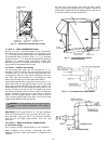
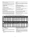
II. STEP 2 — RIG AND PLACE UNIT
Inspect unit for transportation damage. File any claim with
transportation agency.
Do not drop unit; keep upright. Spreader bars are not
required if top crating is left on unit. Use spreader bars over
unit to prevent sling or cable damage. Rollers may be used to
move unit across a roof. Level by using unit frame as a refer-
ence; leveling tolerance is ±
1
/
16
in. per linear ft in any direc-
tion. See Fig. 3 for additional information. Unit operating
weight is shown in Table 1.
Four lifting holes are provided in ends of unit base rails as
shown in Fig. 3. Refer to rigging instructions on unit.
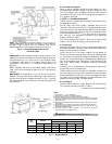
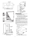
A. Positioning
Maintain clearance, per Fig. 4 and 5, around and above unit
to provide minimum distance from combustible materials,
proper airflow, and service access.
Do not install unit in an indoor location. Do not locate air
inlets near exhaust vents or other sources of contaminated
air. For proper unit operation, adequate combustion and ven-
tilation air must be provided in accordance with Section 5.3
(Air for Combustion and Ventilation) of the National Fuel
Gas Code, ANSI Z223.1 (American National Standards
Institute).
Although unit is weatherproof, guard against water from
higher level runoff and overhangs.
Locate mechanical draft system flue assembly at least 4 ft
from any opening through which combustion products could
enter the building, and at least 4 ft from any adjacent build-
ing. When unit is located adjacent to public walkways, flue
assembly must be at least 7 ft above grade.
B. Roof Mount
Check building codes for weight distribution requirements.
Unit operating weight is shown in Table 1.
Instructions continued on page 8.
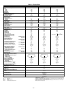
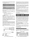
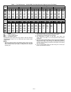
UNIT
581A
MAXIMUM SHIPPING
WEIGHT
DIMENSIONS
AB
lb kg ft-in. mm ft-in. mm
155
1725 782 6-11
1
/
2
2121 4-0 1219
180
1800 816 6-11
1
/
2
2121 3-2 964
240
1900 862 6-11
1
/
2
2121 3-4 1016
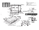
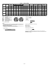
Fig. 3 — Rigging Details
NOTES:
1. Dimensions in ( ) are in millimeters.
2. Refer to Fig. 4 and 5 for unit operating weights.
3. Remove boards at ends of unit and runners prior to rigging.
4. Rig by inserting hooks into unit base rails as shown. Use corner post from
packaging to protect coil from damage. Use bumper boards for spreader
bars on all units.
5. Weights do not include optional economizer. Add 110 lb (50 kg) for econo-
mizer weight.
6. Weights given are for aluminum evaporator and condenser coil plate fins.
7. Add 75 lb (34 kg) for crating on 581A155 and 180 units. Add 135 lb (61 kg)
for crating on 581A240 units.
8. Add 150 lb (68 kg) for copper condenser coil. Add 280 lb (127 kg) for
copper condenser and evaporator coils.
CAUTION:
All panels must be in place when rigging.
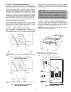
NOTE:
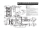
For preassembled horizontal adapter roof curb part no.
(CRRFCURB013A00), the accessory kit includes a factory-designed,
high-static, regain transition duct. For horizontal curb part no.
CRRFCURB012A00, a field-supplied transition duct is required.
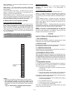
Fig. 2 — Horizontal Adapter Roof Curbs
and Roof Curbs