


35
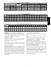
exists, the thermal protector is open. The control de--energizes the
compressor contactor for 15 minutes, but continues to operate the
outdoor fan. The control Status LED will flash the appropriate
code shown in Table 4. After 15 minutes, with a call for low or
high stage cooling, the compressor contactor is energized. If the
thermal protector has not re--set, the outdoor fan is turned off. If
the call for cooling continues, the control will energize the
compressor contactor every 15 minutes. If the therma l protector
closes (at the next 15 minute interval), check the unit will resume
operation.
If the thermal cutout trips for three consecutive cycles, then unit
operation is locked out for 4 hours and the appropriate fault code is
displayed.
NO 230V AT COMPRESSOR
If the compressor voltage is not sensed when the compressor
should be starting, the contactor may be stuck open or there is a
wiring error. The control will flash the appropriate fault code.
Check the contactor and control box wiring.
TROUBLESHOOTING UNIT FOR PROPER SWITCHING
BETWEEN LOW & HIGH STAGES
Check the suction pressures at the service valv es. Suction pressure
should be reduced by 3 --10% when switching from low to high
capacity.
NOTE: The liquid pressures are very similar between low and
high stage operation, so liquid pressure should not be used for
troubleshooting.
Compressor current should increase 20--45% when switching from
low to high stage. The compressor solenoid, when energized in
high stage, should measure 24vac.
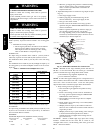
COMPRESSOR INTERNAL RELIEF
The compressor is protected by an internal pr essure relief (IPR)
which relieves discharge gas into compressor shell when
differential between suction a nd discharge pressures exceeds 550 --
625 psi. The compressor is also protected by an internal overload
attached to motor windi ngs.
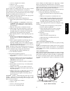
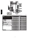
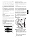
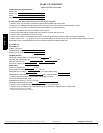
TEMPERATURE THERMISTORS
Thermistors are electronic dev ices which s ense temperature. As the
temperature i ncreases, the resistance decreases. Thermistors are
used to sense outdoor ambient (OAT) and coil temperature (OCT).
Refer to Fig. 28 for resistance values versus temperature. See Fig.
29 for OCT location.
If the outdoor ambient or coil thermistor should fail, the HP/AC
control will flash the appropriate fault code (See Table 4).
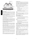
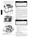
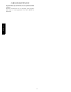
IMPORTANT: Coil thermistor is factory mounted. Check to
insure thermistor is mounted properly. Outdoor air thermistor
(OAT) is field mounted and connected. Verify that the OAT has
been properly installed.
0
10
20
30
40
50
60
70
80
90
0 20 40 60 80 100 120
TEMPERATURE (DEG. F)
RESISTANCE (KOHMS)
THERMISTOR CURVE
A91431
Fig. 28 -- Resistance Values Versus Temperatur e
THERMISTOR SENSOR COMPARISON
The control continuously monitors and compares the outdoor air
temperature sensor and outdoor coil temperature sensor to ensure
proper operating conditions. The comparison is:
S In cooling mode, if the outdoor air sensor indicates ≥ 10 _F
(5.5_C) warmer than the coil sensor (or) the outdoor air sensor
indi cates ≥ 20_F(11.0_C) cooler than the coil sensor, the sensors
are out of range.
S In heating if the outdoor air sensor indicates ≥ 35_F (19.3_C)
warmer than the coil sensor (or) the outdoor air sensor indicates
≥ 10_F(5.5_C) cool er than the coil sensor, the sensors are out of
range.
If the sensors are out of range, the control will flash the appropriate
fault code as shown in Table 4.
The thermistor comparison is not performed during low ambient
cooling operation.
FAILED THERMISTOR DEFAULT OPERATION
Factory defaults have been provided in the event of failure of
outdoor air thermistor and/or coil thermistor.
If the OAT sensor should fail, low ambient cooling will not be
allowed and the one--minute outdoor fan off delay will not occur.
Defrost will be initiated based on coil temperature and time.
If the OCT sensor should fail, low ambient cooling will not be
allowed. Defrost will occur at each time interval dur ing heating
operation, but will terminate after 5 minutes.
If there is a thermistor out of range error , defrost will occur at each
time interval during heating operation, but will terminate after 5
minutes.
Refer to the Troubleshooting Chart (Table 9 and 10) for additional
troubleshooting information.
A06311
Fig. 29 -- Outdoor Coil Thermistor (OCT) Attachment
FINAL CHECKS
IMPORTANT: Before leaving job, be sure to do the following:
1. Ensure that all wiring is rout ed away from tubing and sheet
metal edges to prevent rub--through or wire pinching.
2. Ensure that all wiring and tubing is secure in unit before
addi ng panels and covers. Securely fasten all panels and
covers.
3. Tighten service valve stem caps to 1/2 --turn past finger
tight.
4. Leave Users Manual with owner. Explain system operation
and periodic main tenance requirements outlined in manual.
5. Fill out Start--U p Checklist located at the back of this
manual and place in customer file.
577D-- -- A