


34
Exposure, even if immediately cleaned up, may cause
embrittlement (leading to c racking) to occur in one year or more.
When performing any service that may risk exposure of
compressor oil to the roof, take appropriate precautions to protect
roofing. Procedures which risk oil leakage include, but are not
limited to, compressor r eplacement, repairing refrigerant leaks, and
replacing refrigerant components such as filter drier, pressure
switch, metering devi ce, coil, accumulator, or reversing valve.
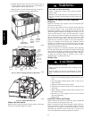
Synthetic Roof Precautionary
Procedure
1. Cover extended roof working area with an impermeable
polyethylene (plastic) drip cloth or tarp. Cover an
approximate 10 X 10 ft (3x3 m) area.
2. Cover area in front of the unit service panel with a terry
cloth shop towel to absorb lubricant spills and prevent
run--offs, and protect drop cloth from tears caused by tool s
or components.
3. Place terry cloth shop towel inside unit immediately under
component(s) to be serviced and prevent lubricant run--offs
through the louvered openings in the unit base.
4. Perform required service.
5. Remove and dispose of any oil--contaminated material per
local codes.
LIQU ID--LINE FILTER DRIER
The f ilter drier is specifically designed to operate with Puron. Use
only factory--authorized components. Filter drier must be repl aced
whenever the r efrigerant system is opened. When removing a f ilter
drier, use a tubing cutter to cut the drier from the system. Do not
uns weat a filter drier from the system. Heat from unsweatin g will
release moisture and contaminants from drier into system .
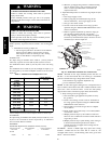
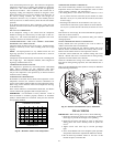
PURON (R--410A) REFRIGERANT CHARGING
Refer to unit information plate and charging chart. Some R--410A
refrigerant cylinders contain a dip tube to allow liquid
refrigerant to flow from cylinder in upright position. For
cylinders equipped with a dip tube, charge Puron units with
cylinder in upr ight position and a commercial metering device in
manifold hose. Charge refrigerant into suction line.
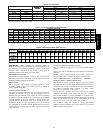
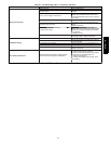
TROUBLESHOOTING
LED DESCRIPTION
LEDs built into Evolution control boards provide installer or
service person information concerning operation and/or fault
condition of the uni t controls and EC M motor. This information is
also available at the system UI in text with basic troubleshooting
instructions. Careful use of information displayed will reduce the
need for extensive manual troubleshooting. See section B in
Start--Up & Troubleshooting and Table 4, as well as the UI
instructions, for additional information. Additional
Troubleshooting information can be found in Table 9 and 10.
MAJOR COMPONENTS
2 --STAGE HP/AC BOARD
The two --stage HP/AC control board controls the following
functions:
-- Low-- and high--stage compressor operation
-- Outdoor fan motor operation
-- Reversing valve operation
-- Defrost operation
-- Low ambient cooling
-- Crankcase heater operation
-- Compressor external protection
-- Pressure switch monitoring (refrigerant)
-- Time delays
FURNACE BOARD
The furnace board controls the following functions:
-- Indoor blower operation
-- G a s v a l v e
-- Inducer motor
-- Remote sparker module
-- Pressure switch monitoring (gas)
SYSTEMS COMMUNICATION FAILURE
If communication with the Evolution Con trol is lost with the UI,
the controls will flash the appropriate fault codes. Check the wiring
to the UI, indoor and outdoor units.
MODEL P LUG
The HP/AC control board must have a valid model plug to operate.
If a valid model plug is not detected, it will not operate and the
control will flash the appropriate fault code, shown in Table 4.
PRESSURE SWITCH PROTECTION --REFRIGERANT
The unit is equipped with high-- and low --pressure switches. If the
control senses the opening of a high -- or low--pressure switch, it
will respond as follows:
1. De--energize the compressor contactor (HPS1 & LPS) or the
compressor solenoid contactor (HPS2).
2. Keep the outdoor fan operating for 15 minutes.
3. Display the appropriate fault codes.
4. After a 15 minute delay, i f there is still a call for cooling a nd
the LPS or HPS is reset, t he compressor contactor is
energized.
5. If LPS or HPS has not closed after a 15 minute delay, the
outdoor fan is turned off. If the open switch closes anytime
after the 15--minute delay, then resume operation with a call
for cooling.
6. If LPS or HPS trips 3 consecutive cycles, the unit operation
is locked out for 4 hours.
7. In the event of a high--pressure switch trip or high pressure
lockout, check the refrigerant charge, outdoor fan operation
and outdoor coil for airflow restrictions.
8. In the event of a low--pressure switch trip or low pressure
lockout, check the refrigerant charge and indoor airflow.
CONTROL FAULT
If the HP/AC control board has failed, the control will flash the
appropriate fault code (See Table 4). The control board should be
replaced.
BROWN OUT PROTECTION
If the line voltage is less than 187v for at least 4 seconds, the
appr opriate compressor contactor and fan relay are de--energized.
Compressor and fan operation are not allowed until voltage is a
minimum of 190v. The control will flash the appropriate fault
code (See Table 4).
230V LINE (POWER DISCONNECT) DETECTION
If there is no 230v at the compressor contactor when the unit is
powered and cooling demand exists, the appropriate error code is
displayed. Verify that the disconnect is closed and 230v wiring is
connected to the unit.
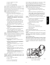
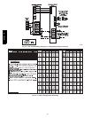
COMPRESSOR VOLTAGE SENSING
The control board input terminals VS and L2 (See Fig. 18) are
used to detect compressor voltage status, and alert the user of
potential problems. The control continuously monitors the high
voltage on the run capacitor of the compressor motor. Voltage
should be present any time the compressor contactor is energized,
and voltage should not be present when the contactor is
de--energized.
CONTACTOR SHORTED DETECTION
If there is c ompressor voltage sensed when there is no demand for
compressor operation, the contactor may be stuck closed or there is
a wiring error. The control will flash the appropriate fault code.
COMPRESSOR THERMAL CUTOUT
If the control senses the compressor voltage after start-- up, and is
then absent for 10 consecutive seconds while cooling demand
577D-- -- A