


10
2. Avoid abrupt duct size increases and reductions. Abrupt
change in duct size a dversely af fects air pe rformance.
IMPORTANT: Use flexible connectors between ductwork and
unit to prevent transmission of vibration. Use suitable gaskets to
ensure weather tight and airtight seal. When electric heat is
installed, use fireproof canvas (or similar heat resistant material)
connector between ductwork and unit discharge connection. If
flexible duct is used, insert a sheet metal s leeve inside duct. Heat
resistant duct connector (or sheet metal sleeve) must extend 24--in.
(610 mm) from electric heater element.
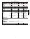
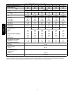
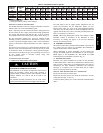
3. Size ductwork for max possible air flow (See Table 1).
4. Seal, insulate, and weatherproof all external ductwork. Seal,
insulate and cover with a vapor barrier all ductwork passing
through conditioned spaces. Follow latest Sheet Metal and
Air Conditioning Contractors National Association
(SMACNA) and Air Conditioning Contractors Association
(ACC A) minimum installation standa rds for residential
heating and air conditioning systems.
5. Secure all ducts to building structure. Flash, weatherproof,
and vibration--isolate duct openings in wall or roof
according t o good construction practices.
6. Read unit rating plate for any required clearances around
ductwork.
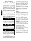
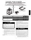
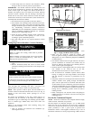
Config uring Units for Downflow (Vertical ) Discharg e
ELECTRICAL SHOCK HAZARD
Failure to follow this warning could result in personal
injury or death.
Before installing or servicing system, always tur n off main
power to system and install lockout tag. There may be
more than one disconnect switch.
!
WARNING
1. Op en all electrical disconnects before starting any service
work.
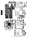
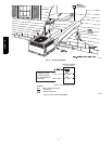
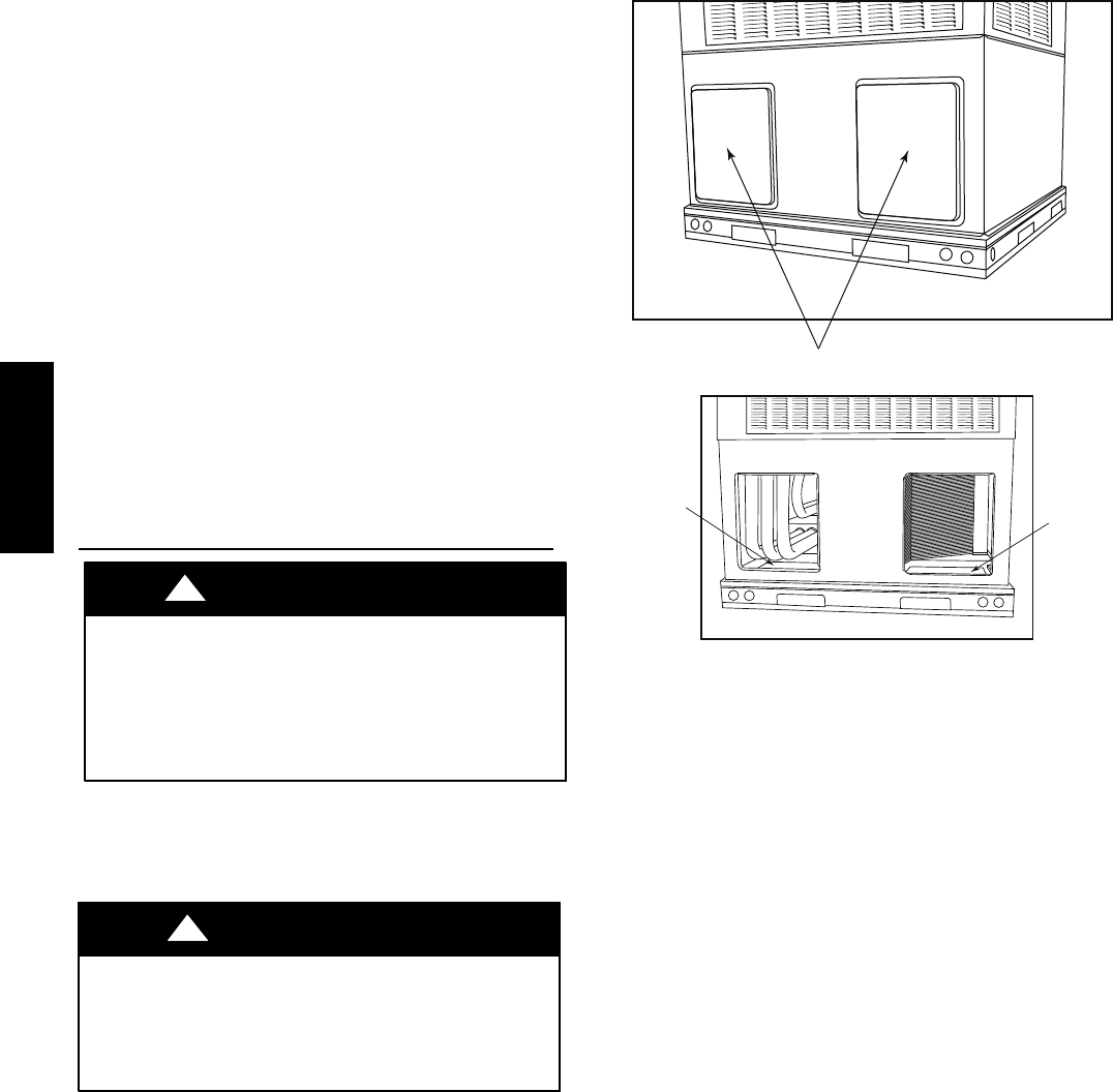
2. Remove horizontal (metal) duc t covers to access vertical
(downflow) discharge duct knockouts in unit basepan. (See
Fig. 8.)
PROPERTY DAMAGE HAZARD
Failure to follow this caution may result in property damage.
Collect ALL screws that were removed. Do not leave screws
on rooftop as permanent damage to the roof may occur.
CAUTION
!
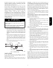
To remove downflow return and supply knockout covers, break
front and right side connecting tabs with a screwdriver and
hammer. Push cove r down t o break rear and left side tabs.
NOTE: These panels are held in place with tabs similar to an
electrical knockout. Reinstall horizontal duct covers (see Fig. 8)
shipped on unit from factory. Insure openings are air and
watertight.
The design and installation of the duct system must be in
accordance with the standards of the NFPA for installation of
nonresidence--type air conditioning and ventilating systems, NFPA
90A or residence-- type, NFPA 90B; and/or local codes and
ordinances.
Adhere to the following criteria when selecting, sizing, and
installing the duct s ystem:
1. Units are shipped for horizontal duct installation (by
removing duct covers).
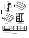
Horizontal Duct Covers
A09076
Basepan
Downflow
(Vertical)
Supply
Knockout
Basepan
Downflow
(Vertical)
Return
Knockout
A09077
Fig. 8 -- Supply and Return Duct Opening
2. Select and size ductwork, supply--air registers, and
return--air grilles according to American Society of Heating,
Refrigeration and Air Conditioning Engineers (ASHRAE)
recommendations.
3. Use flexible transition betw een rigid ductwork and unit to
prevent transmission of vibration. The transition may be
screwed or bolted to duct flanges. Use suitable gaskets to
ensure weather--tight and airtight seal.
4. All units must have field--s upplied filters or accessory filter
rack installed i n th e return--air side of the unit.
Recommended s izes for filters are shown in Table 1.
5. Size all ductwork for maximum required airflow (either
heating or cooling) for unit being installed. Avoid abrupt
duc t size inc reases or decreases or performan ce may be
affected.
6. Adequately insulate and weatherproof all ductwork located
outdoors. Insulate ducts passing through unconditioned
space, and use va por barrier in accordance with latest issue
of Sheet Metal and Air Conditioning Contractors National
Association (SMACNA) and Air Conditioning Contractors
of America ( ACCA) minimum installation standards for
heating and air conditioning systems. Secure all ducts to
building structure.
7. Flash, weatherproof, and vibration isolate all openings in
building structure in accordance with local codes and good
building practices.
Provide for Condensate Disposal
NOTE: Ensure that condensate--water disposal methods comply
with local codes, restrictions, and practices.
The units dispose of condensate through a 3/4 --in. NPT female
fitting that exits on the com pressor end of the unit. Condensate
water can be drained directly onto the roof in rooftop installations
(where permitted) or onto a gr avel apron in ground level
installations. Install a field--supplied condensate trap at end of
condensate connection to ensure proper drainage. Make sure that
577D-- -- A