


11
the outlet of the trap is at least 1 in. (25 mm) lower than the
drain --pan condensate connection to prevent the pan from
overflowing. Prime the trap with water. When using a gravel apron,
make sure it slopes away from the unit.
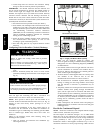
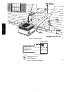
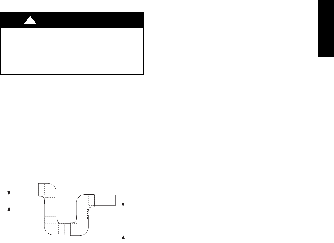
If the installation requires draining the condensate water away from
the unit, install a field--supplied 2--in. (51 mm) trap at the
condensate connection to ensure proper drainage. Condensate trap
is available as an accessory or is field--supplied. Make sure that the
outlet of the trap is at least 1 in. (25 mm) lower than the unit
drain --pan condensate connection to prevent the pan from
overflowing. Connect a drain tube using a minimum of
field--supplied 3/4 -- in. PVC or field--supplied 3/4 -- in. copper pipe
at outlet end of the 2 --in. (51 mm) trap (See Fig. 9). Do not
undersize the tube. Pitch the drain tube downward at a slope of at
least 1 in. for every 10 f t. (3 m) of horizontal run. Be sure to check
the drain trough for leaks. Prime the trap at the beginning of the
cooling season start--up.
Install Flue Hood
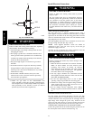
CARBON MONOXIDE POISONING HAZARD
Failure to follow this warning could result in personal
injury or death.
The venting system is designed to ensure proper venting.
The flue hood assembly must be installed as indicated in
this section of the unit installation i nstructions.
!
WARNING
Install the flue hood as follows:
1. Th is installation must conf orm with local building codes
and with the National Fuel Gas Code (NFGC), NFPA
54/ANSI Z223.1 (in Canada, CAN/CSA B149.1, and
B149.2) or latest revision. Refer to provincial and local
plumbing or wastewater codes and other applicable local
codes.
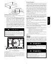
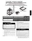
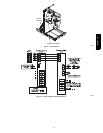
2. Remove flue hood from shipping location (inside the return
section of the blower compartment--See Fig. 8) . Remove the
return duct cover to locate the flue hood. Remove two
screws on flue panel. Place flue hood assembly over flue
panel. Orient screw holes in flue hood with holes in the flue
panel.
3. Secure flue hood to flue panel by inserting a single screw on
the top and the bottom of the hood.
TRAP
OUTLET
1-in. (25 mm) min.
2-in. (51 mm) min.
A09052
Fig. 9 -- Condensate Trap
Install Gas Piping
The gas supply pipe enters the unit through the access hole
provided. The gas connection to the unit is made to the 1/2--in.
FPT gas inlet on the gas valve.
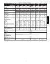
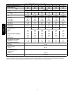
Install a gas supply line that runs to the heating section. Refer to
Table 2 and the current edition of NFGC in the U.S. and the current
NSCNGPIC in Canada. Do not use cast--iron pipe. It is
recomme nded that a black iron pipe is used. Check the local utility
for recommendations concerning existing lines. Size gas supply
piping for 0.5 IN. W.C. maximum pressure drop. Never use pipe
smaller than the 1/2--in. FPT gas inlet on the unit gas valve.
For natural gas applications, the gas pressure at unit gas connection
must not be less than 4.0 IN. W.C. or greater than 13 IN. W.C.
while the unit is operating. For propane applications, refer to
propane conversion kit instructions.
A 1/8--in. (3.2 mm) NPT plugged tapping, accessible for test gauge
connection, must be installed immediately upstream of the gas
supply connection to the gas valve and downstream of manual
equipment shutoff valve.
When installing t he gas s upply line, observe local codes pertaining
to gas pipe installations. Refer to the NFPA 54/ANSI Z223.1 --2009
(in Canada, CAN/CSA B149.1).
NOTE: In the state of Massachusetts:
1. Gas supply connections MUST be performed by a licensed
plumber or gas fitter.
2. When flexible connectors are used, the maximum length
shall not exceed 36 in. ( 915 mm).
3. When lever handle type manual equipment shutoff valves
are used, they shall be T--handle valves.
4. The use of copper tubing for gas piping is NOT approved
by the state of Massachusetts.
In the absence of local bu ilding codes, adhere to the f ollowing
pertinent recommendations:
1. Avoid low spots in long runs of pipe. Grade all pipe 1/4 in.
(6.35 mm) for every 15 ft (4.6 m) of length to prevent traps.
Grade all horizontal runs downward to risers. Use risers to
connect to heating section and to meter.
2. Protect all segments of piping system against physical and
thermal damage. Support all piping with appropriate straps,
hangers, etc. Use a minimum of one hanger every 6 ft. (1.8
m). For pipe sizes larger than 1/2 in., follow
recommendations of national codes.
3. Apply joint compound (pipe dope) sparingly and only to
male threads of joint when making pipe connections. Use
only pipe dope that is resistant to action of liquefied
petroleum gases as specified by local and/or national codes.
Never use Teflon tape.
4. Install sediment trap in riser leading to heating section (Se e
Fig. 10). This drip leg functions as a trap for dirt and
condensate.
5. Install an accessible, external, manual main shutoff valve in
gas supply pipe within 6 ft (1.8 m) of heating section.
6. Install ground--joint union close to heating section between
unit manual shutoff and external manual main shut off
valve.
7. Pressure test all gas piping in accordance with local and
national plumbing and gas codes before connecting piping
to unit.
NOTE: Pressure test the gas supply system after the gas supply
piping is connected to the gas valve. The supply piping must be
disconnected from the gas valve during the testing of the piping
systems when test pressure is in excess of 0.5 psig. Pressure test the
gas supply piping system at pressures equal to or less than 0.5 psig.
The uni t heating section must be isolated from the gas piping
system by closing the external main manual shutoff valve and
slightly opening the ground--joint union.
577D-- -- A