


2
SAFETY CONSIDERATIONS
Improper installation, adjustment, alteration, service maintenance,
or use can cause explosion, fire, electrical shock, or other
conditions which may cause death, personal injury, or property
damage. Consult a qualified installer, service agency, or your
distributor or branch for information or assistance. The qualified
installer or agency mus t use factory--authorized kits or accessories
when modifying this product. Refer to the individual instructions
packaged with the kits or accessories when installing.
Follow all safety codes. Wear safety glasses, protective clothing,
and work gloves. Have a fire extinguisher available. Read these
instructions thoroughly and follow all warnings or cautions
included in literature an d attached to the unit. consult local
building codes, the current editions of the National Fuel Gas Code
(NFGC) NFPA 54/ANSI Z223.1, and the National Electrical Code
(NEC) NFPA 70.
In Canada refer to the current editions of the National Standards of
Canada CAN/CSA --B149.1 and .2 Natural Gas and Propane
Installation codes, and Canadian Electrical Co de CSA C22.1
Recognize safety information. This is the safety--alert symbol
.
When you see this symbol on the unit and in instructions or manu-
als, be alert to the potential for personal injury. Understand these
signal words: DANGER, WARNING, and CAUTION. These
words are used with the safety--alert symbol. DANGER identifies
the most s erious hazards which will result in severe personal injury
or death. WARNING signi fies hazards which could result in per-
sonal injury or death. CAUTION is used to identify unsafe practic-
es which may result in minor personal injury or product and prop-
erty damage. NOTE is used to highlight suggestions which will
result in enhanced installation, reliability, or operation.
ELECTRICAL SHOCK HAZARD
Failure to follow this warning could result in personal
injury or death.
Before installing or servicing system, always tur n off main
power to system and install lockout tag. There may be
more than one disconnect switch. Turn off accessory heater
power switch if applicable.
!
WARNING
UNIT OPERATION AND SAFETY HAZARD
Failure to follow this warning could result in personal
injury or equip ment damage.
Puron (R--410A) systems operate at higher pressures than
standard R--22 systems. DO NOT use R --22 service
equipment or components on Puron (R--410A) equipment.
Ensure service equipment is rated for Puron (R--410A).
WARNING
!
CUT HAZARD
Failure to follow this caution may result in personal injury.
When removing access panels or performing maintenance
functions inside your unit, be aware of sharp sheet metal
parts and screws. Although special care is taken to reduce
sharp edge s to a minimum, be extremely careful when
handling parts or reaching into the unit.
CAUTION
!
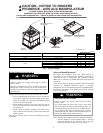
INTRODUCTION
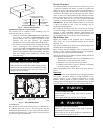
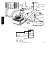
The 577D----A packaged unit is a fully self--contained combination
Category I gas heating/electric air conditioner designed for outdoor
installation (See Fig. 1). Standard units are shipped in a
horizontal--discharge configuration for installation on a rooftop, or
on cement slab (See Fig. 4 for roof curb dimensions). Standard
units can be converted to downflow (vertical) discharge
configurations for rooftop applications.
Mode ls with an N i n the thirteen th position of the mode l number
are dedicated Low NOx units designed for California installations.
These models meet the California maximum oxides of nitrogen
(NOx) emissions requirements of 40 nanograms/joule or less as
shipped from the factory and must be installed in California Air
Quality Management Districts or any other regions in North
America where a Low NO x rule exists.
In gas heating mode, this unit is designed for a minimum
continuous return--air temperature of 55_F(13_C) db and a
maximum continuous return--air temperature of 80_F(27_C) db.
Failure to follow these return--air temperature limits may affect
reliability of heat exchangers, motors, and other components.
NOTE: Low NOx requirements apply only to natural gas
installations.
RECEIVING AND INSTALLATION
Check Equipment
IDENTIFY UNIT
The unit model number and serial number are printed on the unit
informative plate. Check this informatio n against shipping papers.
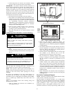
INSPECT SHIPMENT
Inspect for shipping damage before removing packaging material.
If unit appears to be dam aged or is torn loose from its anchorage,
have it examined by transportation inspectors before removal.
Forward claim papers directly to transportation company .
Manufacturer is not responsible for any damage incurred in transit.
Check all items against shipping list. Immediately notify the
nearest distributor office if any item is missing. To prevent loss or
damage, leave all parts in original packages until installation.
If the unit is to be mounted on a curb in a downflow application,
review “Configuring Units for Downflow Discharge” to determine
which method is to be used to remove the downflow panels before
riggi ng and lifting into place. The panel removal process may
require the unit to be on the ground.
Provide Unit Support
IMPORTANT: The uni t must be secured to the curb by installin g
screws through the bottom of the curb flange and into the unit base
rails. When installing large base units onto the common curb, th e
screws must be installed before allowing the full weight of the unit
to rest on the curb. A minimum of six screws are required for large
base units. Failure to secure unit properly could result in an
unstable unit. See Warning near Rigging/Lifting information and
accessory curb instructions for mo re details.
For hurricane tie downs, contact distributor for details and PE
(Professional Engineering) Certificate, if required.
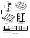
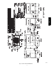
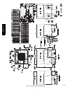
ROOF CURB
Install accessory roof curb in accordance with instructions shipped
with curb (See Fig. 4). Install insulation, cant strips, roofing, and
flashing. Ductwork must be attached to curb.
IMPORTANT: The gasketing of the unit to the roof curb is
critical for a water tight seal. Install gasketing material supplied
with the roof curb. Improperly applied gasketing also can result in
air leaks and poor unit performance.
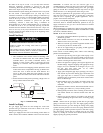
Curb should be level to within 1/4 in. (6.35 m) (See Fig. 2). This is
necessary for unit drain to function properly. Refer to accessory
roof curb installation instructions for additional information as
required.
577D-- -- A