


13
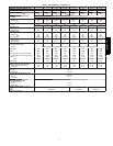
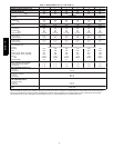
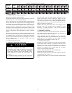
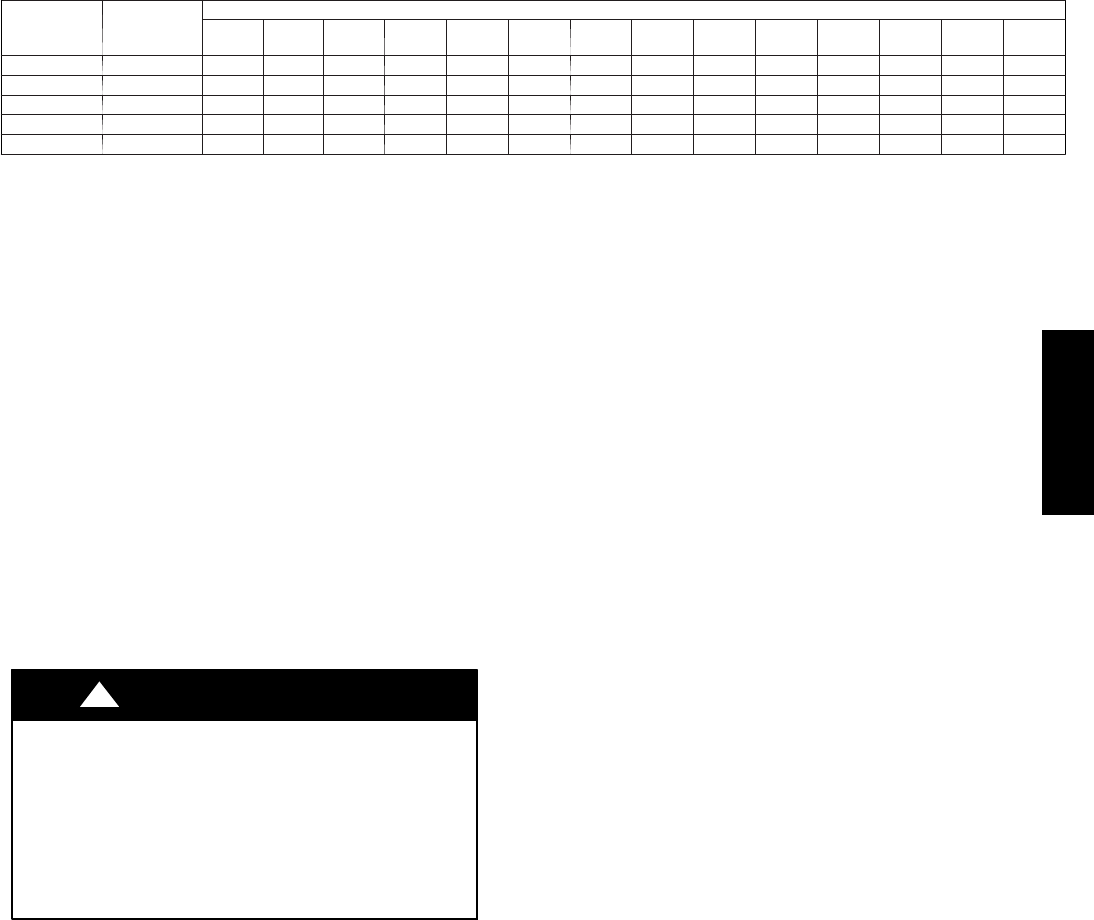
Table 2 – Maximum Gas Flow Capacity*
NOMINAL
IRON PIPE
SIZE (IN.)
INTERNAL
DIAMETER
(IN.)
LENGTH OF PIPE ft (m)†
10
(3.0)
20
(6.1)
30
(9.1)
40
(12.1)
50
(15.2)
60
(18.3)
70
(21.3)
80
(24.4)
90
(27.4)
100
(30.5)
125
(38.1)
150
(45.7)
175
(53.3)
200
(61.0)
1/2 .622 175 120 97 82 73 66 61 57 53 50 44 40 — —
3/4 .824 360 250 200 170 151 138 125 118 110 103 93 84 77 72
1 1.049 680 465 375 320 285 260 240 220 205 195 175 160 145 135
1 --- 1/ 4 1.380 1400 950 770 600 580 530 490 460 430 400 360 325 300 280
1 --- 1/ 2 1.610 2100 1460 1180 990 900 810 750 690 650 620 550 500 460 430
*Capacity of pipe in cu ft of gas per hr for gas pressure of 0.5 psig or less. Pressure d rop of 0.5---IN . W.C . (based on a 0.60 specific gravity gas). Refer toTable2
and NFPA 54/ANSI Z223.1.
{ This length includes an ordinary number of fittings.
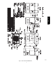
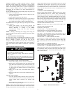
ROUTING CONTROL POWER WIRES
For detailed instruction on the low voltage connections to the User
Interface (UI), refer to the UI installation guide.
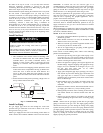
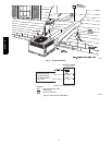
Form a drip--loop with the control leads before routing them into
the unit. Route the low voltage control leads through grommeted,
low--voltage hole provided into unit (See Fig. 5 and 6). Connect
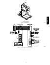
user interface leads to unit control power leads as shown in Fig. 14.
The unit transformer supplies 24--v power for complete system
including accessory electrical heater. Transformer is factory wired
for 230--v operation. If supply voltage is 208--v, rewire transformer
primary a s described in Special Procedures for 208--v Operation
section.
The furnace board is fused by a board--mounted automotive fuse
placed in series with transfor mer SE C1 and R circuit. The C circuit
of transformer circuit is referenced to chassis ground through a
printed circuit run at SEC2 and gas valve grounding wire. Check to
be sure control board is mounted securely using both
factory--installed s crews.
ACCESSORY INSTALLATION
A. Outdoor Air Temperature Sensor (OAT)
EQUIPMENT OPERATION HAZARD
The installation of an outdoor air temperature sensor (OAT)
using the Evolution control board OAT terminals is
required. Many Evolution features (auto humidity control,
comfort rollback, etc.) will be lost if the OAT is no t
connected.
For detailed mounting instructions for the OAT sensor,
please refer installation instructions shipped with the OAT.
!
CAUTION
The OAT input is used to supply outdoor temperature data for
system level functions and for temperature display on User
Interface (UI). Using two wires of th e field--supplied thermostat
wire cable, wire the ends of the two black OAT pigtails. Wire the
opposite ends of these two wires to the OAT provided with the UI.
There is no polarity to be observed.
NOTE: Mis--wiring OAT inputs will not cause damage to either
Evolution control or thermisto r. If the thermistor is wired
incorrectly, no reading will appear at UI. Re--wire thermistor
correctly for normal operation.
B. Humidifier Connections
The furnace control board terminal marked HUM is provided for
low voltage (24--vac) control of a humidifier. No hum idistat is
required as UI monitors indoor humidity.
When commanded to operate humidifier, the unit control will
energize the HUM output to turn humidifier on and de--energize
HUM output to turn humidifier off. Wire HUM and COM
terminals directly to humidifier as show n in Fig. 14.
C. Electronic Air Cleaner
Electronic Air Cleaner terminals are provided on the Evolution
Control Board (EAC--1 and EAC--2). While these terminals can be
used to power a 230V EAC, it is recommended that any EAC be
installed per the EAC installation instructions and connected
separately to a standard 115V or 230V outlet with an airflow
sensor to control operation of the EAC.
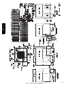
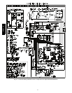
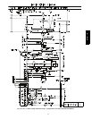
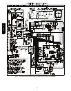
SPECIAL PROCEDURES FOR 208--V OPERATION
Be sure unit disconnect switch is open.
Disconnect the black pr imary lead from the transformer. Se e unit
wiring label (See Fig. 16 and 17).
Connect the black primary lead to the transformer terminal labeled
208--v.
577D-- -- A