


17
emergency heating or cooling operation using a common
thermostat and the terminal strip connections on the two control
boards (See Non --Communicating Emergency Cooling/Heating
Mode) and will display Status Code 16, System Communication
Fault, on amber STATUS LED. No further troubleshooting
information will be available at UI until communications are
re--established.
If either COMM LED does not light within proper time period and
status codes are not displayed;
1. Check system transformer high-- and low-- voltage to be sure
the system is powered.
2. Check ABCD connection on both boards.
3. Check fuse on furnace board to be sure it is not blown. If
fuse is open, check system wiring before replacing it to be
sure a shor t do es not cause a failure of repl acement fuse.
If COMM LED does not light within proper time period and status
code is displayed:
1. Check system wiring to be sure UI is powered and
connections are made A to A, B to B, etc. and wiring is not
shorted. Miswiring or shorting of the ABCD
communications wiring will not allow successful
communications.
NOTE: Shorting or misw iring low--voltage system wiring will
not cause damage to unit control or UI but may cause low voltage
fuse to open.
C. Indoor Fan Motor Troubleshooting
The indoor fan is driven by an ECM motor consisting of two parts:
the control module and the motor winding section. Do not assume
motor or module is defective if it will not start. Use the
designed--in LED information aids and follow troubleshooting
steps described below before replacing motor control module or
entire motor. Motor control module is available as a replacement
part.
VERIFY MOTOR WINDING SECTION
ELECTRICAL SHOCK HAZARD
Failure to follow this warning could result in personal
injury or death.
After disconnecting power from the ECM motor, wait at
least 5 minutes before removing the control section. Internal
capacitors require time to discharge.
!
WARNING
Before proceed ing to r eplace a motor contro l module:
1. Check motor winding section to be sure it is functional.
2. Remove motor control module section and unplug winding
plug. Motor shaft should turn freely, resistance between any
two motor leads should be similar and resistance between
any motor lead and unpainted motor end should exceed
100,000 ohms.
3. Failing any of these tests, entire ECM motor must be
replaced.
4. Passing all of the tests, motor control module alone can be
replaced.
MOTOR TURNS SLOWLY
1. Low s tatic pr essure loading of blo wer while access panel is
removed will cause bl ower to run slowly. Particularly at low
airflow requests. This is normal, do not assume a fault
exists.
2. Recheck airflow and system static pressure using UI service
screens with access panel in place.
NOTE: Blower motor faults will not cause a lockout of blower
operation. The fan coil control will attempt to run the blower motor
as long as UI maintains a demand for airflow. The control will not
operate electric heaters while a fault condition exists. The control
communicates with the motor at least once every five seconds,
even when the motor is idle. If, during operation, the control does
not communicate with the motor for more than 25 seconds, the
motor will shut itself down and wait for communications to be
reestablishe d.
D. Furnace Control Troubleshooting
Furnace control faults indicated by flashing codes on the amber
system STATUS LED can be resolved using troubleshooting
information provided below. Codes are listed in order of their
priority, highest to lowest. Though multiple faults can exist at any
time, only the highest priority code will be displayed on STATUS
LED. Clearing the indicated faul t when multiple faults exist will
cause the next highest priority Status Code to be flashed. All
existing faults, as well as a faul t history, can be vi ewed at UI.
STATUS CODE CONTINUOUS OFF
Check for 230 VAC at L1 and L2, and 24 VAC at SEC--1 and
SEC--2.
STATUS CODE CONTINUOUS ON
Control has 24 VAC power.
STATUS CODE 11 -- NO PREVIOUS CODE
Stored status codes are erased automatically after 72 hours.
STATUS CODE 12 -- BLOWER ON AFTER POWER UP
(230 VAC or 24 VAC) Blower runs for 90 seconds if unit is
powered up during a call for heat (R--W/W1 clos ed) or (R--W/W1
opens) during blower on--delay period.
STATUS CODE 13 -- LIMIT CIRCUIT LOCKOUT
Lockout occurs if a limit or flame rollout switch is open longer
than 3 minut es or 10 successive limit trips occurred during high
heat. Control will auto reset after three hours. Refer to status code
33.
STATUS CODE 14 -- IGNITION LOCKOUT
Control will auto reset after three hours. Refer to status code 34.
STATUS CODE 15 -- BLOWER MOTOR LOCKOUT
Indi cates the blower failed to reach 250 RPM or the blower failed
to communicate within 30 seconds after being turned ON in two
successive heating cycles. Control will auto reset after 3 hours.
Refer to status code 41.
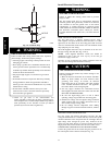
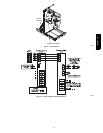
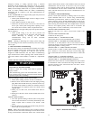
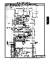
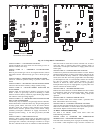
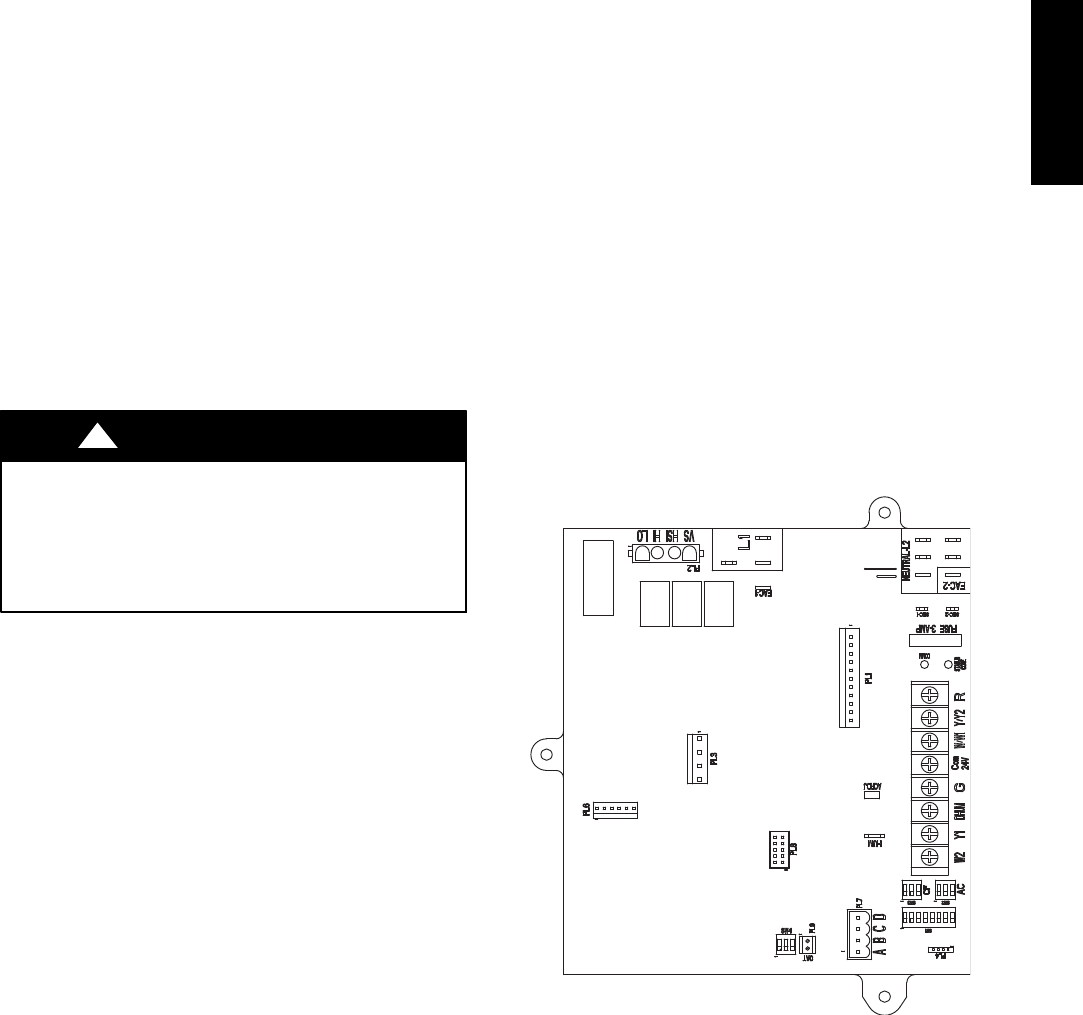
A06026
Fig. 15 -- Detail of Furnace Board
577D-- -- A