


29
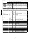
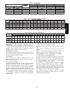
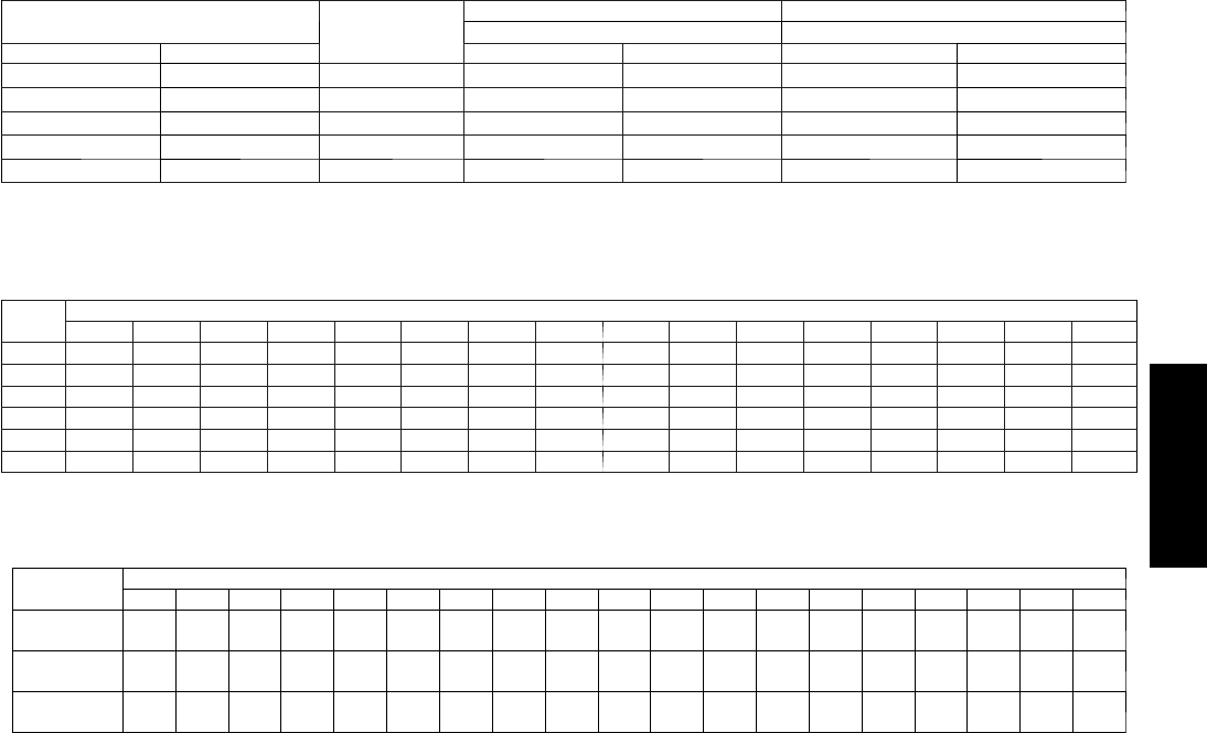
Table 6 – Heating Inputs
HEATING INPUT (BTU/HR)*
NUMBER
OF
GAS SUPPLY PRESSURE (IN. W.C.) MANIFOLD PRESSURE (IN. W.C.)
NUMBER OF
ORIFICES
Natural Natural
High Stage Low Stage
ORIFICES
Min Max High Stage Low Stage
40,000 26,000 2 4.0 13.0 3.2∼ 3.8 1.4 ∼ 2.0
60,000 39,000 3 4.0 13.0 3.2∼ 3.8 1.4 ∼ 2.0
90,000 58,500 3 4.0 13.0 3.2∼ 3.8 1.4 ∼ 2.0
115,000 75,000 3 4.0 13.0 3.2∼ 3. 8 1.4 ∼ 2.0
130,000 84,500 3 4.0 13.0 3.2∼ 3.8 1.4 ∼ 2.0
*Cubic ft of natural gas per hour for gas pressures of .5 psig (14 IN. W .C.) or le ss and a pre ssure drop of .5 IN. W.C. (base d on a .60 specific gravity gas). Ref:
Table 6.2 (b) NPFA 54 / ANSI Z223.1---2009.
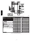
Table 7 – ECM Wet Coil Pressure Drop (IN. W.C.)
UNIT
SIZE
STANDARD CFM (SCFM)
600 700 800 900 1000 1100 1200 1300 1400 1500 1600 1700 1800 1900 2000 2100
24 0.005 0.007 0.010 0.012 0.015 – – – – – – – – – – –
30 – 0.007 0.010 0.012 0.015 0.018 0.021 0.024 – – – – – – – –
36 – – – 0.019 0.023 0.027 0.032 0.037 0.042 0.047 – – – – – –
42 – – – – 0.014 0.017 0.020 0.024 0.027 0.031 0.035 0.039 0.043 – – –
48 – – – – – – 0.027 0.032 0.036 0.041 0.046 0.052 0.057 0.063 0.068 –
60 – – – – – – – – – 0.029 0.032 0.036 0.040 0.045 0.049 0.053
Table 8 – Filter Pressure Drop Table (IN. W.C.)
FILTER SIZE
in. (mm)
CFM
500 600 700 800 900 1000 1100 1200 1300 1400 1500 1600 1700 1800 1900 2000 2100 2200 2300
20X20X1
(508x508x 25)
0.05 0.07 0.08 0.1 0.12 0.13 0.14 0.15 — — — — — — — — — — —
24X30X1
(610x762x 25)
— — — — 0.05 0.6 0.07 0.07 0.08 0.09 0.1 — — — — — — — —
24X36X1
(610x914x 25)
— — — — — — — 0.06 0.07 0.07 0.08 0.09 0.09 0.10 0.11 0.12 0.13 0.14 0.14
IMPORTANT: When evaluating the refrigerant charge, an
indi cated adjustment to the specified factory charge must always be
very minimal. If a substantial adjustment is indicated, an abnormal
condition exists som ewhere in the cooling system, such as
insufficient airflow across either coil or both coils.
REFRIGERANT CHARGE
The amount of refrigerant charge is listed on the unit rating plate
and/or the physical data table. Refer to the Refrigeration Service
Techniques Manual, Refrigerants Section.
NO CHARGE
Check for leak. Use standard evacuating techniques. After
evacuating system, weigh in the specified amount of refrigerant
(refer to system rating plate).
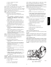
LOW CHARGE COOLING
Use Cooling Charging Chart (Fig. 23). Vary refrigerant until the
conditions of the chart are met. Note that charging charts are
different from type normally used. Charts are based on charging
the units to correct subcooling for the various operating conditions.
Accurate pressure gauge and tem perature sens ing devices are
required. Connect the pressure gauge to the service port on the
suction line. Mount the temperature sensing device on the suction
line and insulate it so that the outdoor ambient does not affect the
reading. Indoor air CFM must be within the normal operating
range of the unit.
TO USE COOLING CHARGING CHARTS
Take the liquid line temperature and read the manifold pressure
gauges.
Refer to the chart to determine what the liquid line tempe rature
should be.
NOTE: If the problem causing the inaccurate readings is a
refrigerant leak, refer to Check for Refrigerant Leaks s ection.
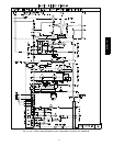
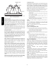
NON--COMMUNICATING EMERGENCY COOLING /
HEATING MODE: 4--WIRE THERMOSTAT
This mode of operation is provided only in the case where the UI
has failed or is otherwise unavailable. If communications cannot be
established with the UI, the Evolution furnace boa rd will enable
the standard thermostat input terminals to allow simple
thermostatic control of the 577D---- A unit.
For control with a standard thermo stat, disconnect the AB CD
connectors from both control boards and using No. 18 AWG
color-- coded, insulated type 90°C minimum or equivalent wire,
make the connections between the standard thermostat, the furnace
board, and the HP/AC board per Fig. 22. Recommend the use of
interconnecting wire with 105C, 600V, 2/64” insulation.
The Evolution control will respond to cooling and heating
demands with the maximum safe airflow based on gas furnace
output and unit cooling capacity.
577D-- -- A