


16
PRE--START--UP
FIRE, EXPLOSION, ELECTRICAL SHOCK AND
ENVIRONMENTAL HAZARD
Failure to follow this warning could result in personal
injury or death and/or property damage.
1. Follow recognized safety practices and wear protective
goggles when checking or servicing refrigerant system.
2. Do not operate compressor or provide any electric power
to unit unless compressor terminal cover is in place and
secured.
3. Do not remove compressor terminal cover until all
electrical sources are disconnected and tagged.
4. Relieve and recover all refrigerant from system before
touching or disturbing anything inside terminal box if
refrigerant leak is suspected around compressor
terminals.
5. Never attempt to repair soldered connection while
refrigerant system is under pressure.
6. Do not use torch to remove any component. System
contains oil and refrigerant under pressure.
7. To remove a component, wear protective goggles and
proceed as follows:
a. Shut off gas supply to unit.
b. Shut off electrical power to unit and install
lockout tag.
c. Relieve and reclaim all refrigerant from s ystem
using both high-- and low--pressure ports.
d. Cut component connecting tubing with tubing
cutter and remove component from unit.
e. Carefully unsweat remaining tubing stubs when
necessary. Oil can ignite when exposed to flame.
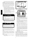
!
WARNING
Use the Start-- Up Checklist supplied at the end of this book and
proceed as follows to insp ect and prepare the un it for initial
start-- up:
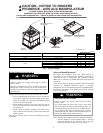
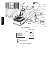
1. Remove all access panels. (See Fi g. 24.)
2. Read and follow instructions on all DANGER, WARNING,
CAUTION, and INFORMATION labels attached to, or
shipped with un it.
3. Make the following inspections:
a. Inspect for s hippi ng and handling damages, such as
broken lines, loose parts, disconnected wires, etc.
b. Inspect for oil at all refrigerant tubing connections and
on unit base. Detecting oil generally indicates a
refrigerant leak. Leak test all refrigerant tubing
connections using electronic leak detector, or
liquid--soap solution. If a refrigerant leak is detected, see
following Check for Refrigerant Leaks section.
c. Inspect all field-- and factory--wiring connections. Be
sure that connections are completed and tight.
d. Ensure wires do not touch refrigerant tubing or sharp
sheet metal edges.
e. Inspect coil fins. If damaged dur ing shipping and
handling, carefully straighten fins with a fin comb.
4. Verify the following conditions:
a. Make sure gas line is free of air. Before lighting the unit
for the first time, perform the following tasks with the
gas valve in the OFF position.
NOTE: If the gas supply pipe was not purged before connecting
the unit, it will be full of air. It is recommended that the ground
joint union be loosened, and the supply line be allowed to purge
until the odor of gas is detected. Never purge gas lines into a
combustion chamber. Immediately upon detection of gas odor,
retighten the union. Allow 5 minutes to elapse, then light unit.
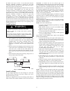
b. Make sure that condenser-- fan blade is correctly
positioned in fan orifice. Top 1/3 of condenser fan blade
should be within fan orifice venturi.
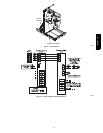
c. Ensure fan hub is positioned correctly with respect to
motor housing (See Fig. 27).
d. Make sure that air f ilter(s) is in place.
e. Make sure that condensate drain trap is filled with water
to ensure prope r drainage.
f. Make sure that all tools and miscellaneous loose parts
have been removed.
5. Compressors are internally spring mounted. Do not loosen
or remove compressor holddown bolts.
6. Each unit system has two Schrader--type ports, one
low--side Schrader fitting located on the suction line, and
one high--side Schrader fitting located on the compressor
discharge line. Be sure that caps on the ports are tight.
START--UP
Unit Start--Up and Troubleshooting
NOTE: Always check high-- and low--voltage supply to the unit
components. Check the integrity of the plug receptacle connections
and unit wiring harness prior to assuming a component failure.
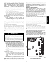
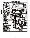
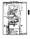
A. LED Description
LEDs built into Evolution control boards provide installer or
service person information concerning operation and/or fault
condition of the uni t controls and EC M motor. This information is
also available at the system UI in text with basic troubleshooting
instructions. Careful use of information displayed will reduce the
need for extensive manual troubleshooting.
Both the furnace and heat pump (HP)/air conditioner (AC) boards
have an amber LED and a green LED. On the HP/AC board, these
are located near the System Communications connector (ABCD)
(lower right corner of the HP/AC board as installed in the unit).
On the furnace board, these are located at the upper right side,
adjacent to the fuse, above the terminal block. The amber LED is
the System Status LED, labeled STATUS . The green LED , labeled
COM M, is used as an indicator of system comm unications status
(See Fig. 15 and 18).
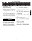
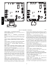
Status Codes will be displayed on the STATUS LED using the
following protocol:
1. The number of short flashes indicates first digit of code.
2. The number of long flashes indicates second digit of code.
3. A short flash is 0.25 seconds on. A long flash is 1 second
on.
4. The time between flashes is 0.25 seconds.
5. The time between last short flash and first long flash is 1
second.
6. The LEDs will be off for 2.5 seconds before repeating code.
7. If multiple status codes are active concurrently, the highest
priority status code is displayed.
B. Control Start--Up and System Communications
Troubleshooting
On power up, green COMM LEDs will be turned off until
successful system communications are established (this should
happen within 10 seconds). Once communications with UI are
successful, both COMM LEDs will be lit and held on. At the same
time, amber STATUS LEDs will be lit and held continuously on
until a request for operating mode is received. The STATU S LED
will be on any time unit is in idle mode.
If, at any time, comm unications are not successful for a pe riod
exceeding 2 min utes, the Ev olution control will only allow
577D-- -- A