


26
CARBON MONOXIDE POISONING HAZARD
Failure to follow this warning could result in personal
injury and/or death.
If the manifold pressure and/or gas rate is not properly
adjusted on HI and LO stages, excess carbon monoxide can
be produced.
!
WARNING
FIRE AND UNIT DAMAGE HAZARD
Failure to follow this warning could result in personal
injury or death and/or property damage.
Unsafe operation of the unit may result if manifold pressure
is outside of the ranges listed in Table 6.
!
WARNING
Gas input rates on rating plate are for installations at altitudes up to
2000 ft (610 m). Input rate must be within ± 2% of rating plate
input.
1. Determine the correct gas input rate.
a. The rated gas inputs shown in Table 6 are for altitudes
from sea level to 2000 ft (610 m) above sea level.
These inputs are based on natural gas with a heating
value of 1025 Btu/ft3 at .60 specific gravity.
IN THE U.S.A.:
The input rating for altitudes above 2,000 ft (610 m) must be
reduced by 4 percent for each 1,000 ft (305 m) a bove sea level.
For installations below 2,000 ft, (610 m) refer to the unit rating
plate.
For installations above 2,000 ft, (610 m) multiply the input by on
the rating plate by the derate multiplier in Table 5 for the correct
input rate.
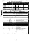
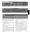
Table 5 – Altitude Derate Multiplier for U. S.A*.
Altitu de ft (m) Percent of Derate
Derate Multiplier
Factor{
0--2000
(0--610)
0 1.00
2001--3000*
(610--914)
8--12 0.90
3001--4000
(915--1219)
12--16 0.86
4001--5000
(1220--1524)
16--20 0.82
5001--6000
(1524--1829)
20--24 0.78
6001--7000
(1829--2134)
24--28 0.74
7001--8000
(2134--2438)
28--32 0.70
8001--9000
(2139--2743)
32--36 0.66
9001--10,000
(2744--3048)
36--40 0.62
* In Canada see Canadian Altitude Adjustment.
{Derate multiplier factors are based on midpoint altitude for altitude range.
IN CANADA:
The input rating for altitudes from 2,000 (610 m) to 4, 500 ft (1372
m) above sea level must be derated 10 percent by an authorized
Gas Conversion Station or Dealer.
EXAMPLE:
90,000 Btuh Input Furnace Installed at 4300 ft (1372 m).
Furnace Input Rate Derate Multiplier Furnace Input Rate
at Sea Level X Factor = at Installation
Altitude
90,000 X 0.90 = 81,000
b. When the gas supply being used has a different heating
value or specific gravity, refer to national and local
codes, or contact your distributor to determine the
requi red orifice size.
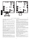
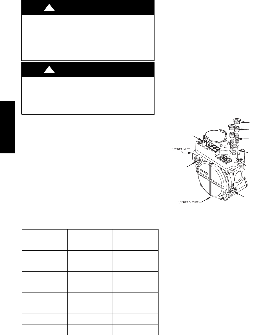
2. Adjust manifold pressure to obtain low stage input rate (See
Fig. 19).
a. Turn off gas supply to unit.
b. Remove pipe plug on manifold (See Fig. 20 and
connect manometer). Turn on gas supply to unit.
c. Turn gas valve switch to ON.
d. Set unit to run for 20 minutes in low--stage gas heat
operation using the ”INSTALLER CHECKOUT” menu
on the User Int erface.
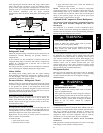
e. Remove regulator adjustment cap from l ow stage gas
valve pressure regulator (See Fig. 19) and turn
low--stage adjusting screw (3/16 or s maller flat--tipped
screwdriver) counterclockwise (out) to decrease rate and
clockwise (in) to increase input rate.
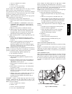
REGULATOR COVER SCREW
PLASTIC ADJUST SCREW
LOW STAGE
GAS PRESSURE
REGULATOR ADJUSTMENT
MANIFOLD
PRESSURE TAP
INLET
PRESSURE TAP
ON/OFF SWITCH
REGULATOR SPRING
HIGH STAGE GAS
PRESSURE REGULATOR
ADJUSTMENT
A04167
Fig. 19 -- Redundant Automatic Gas Control Valve
NOTE: DO NOT set low stage manifold pressure less than 1.4
IN. W.C. or more than 2.0 IN. W.C. for natural gas. If manifold
pressure is outside this range, change main burner orifices.
f. Re--install low stage regulator adjustm ent cap.
g. Leave manometer connected.
NOTE: If orifice hole appears damaged or it is suspected to have
been re--drilled, check or ifice hole with a numbered drill bit of the
correct size. Never re--drill an orifice. A burr--free and squarely
aligned orifice hole is essential for proper flame characteristics.
3. Verify natural gas low stage input rate.
a. Turn off all other gas appliances and pilots served by
the gas meter.
b. If unit is not running, set unit to run for 20 minutes in
low--stage gas heat operation using the ”INSTALLER
CHECKOUT” menu on the UI.
c. Record number of seconds for gas meter to complete
one revolution.
d. Divide number of seconds in step c. into 3600 (number
of seconds in 1 hour).
e. Multiply result of step d. by the number of cubic feet
shown for one revolution of test dial to obtain cubic feet
of gas flow per hour.
f. Multiply result of step f. by Btu heating value of the gas
to obtain total measured input shown in Table 6.
(Consult the local gas supplier if the heating value of
gas is not known).
EXAMPLE: Assume a 90,000 high stage input unit is being
installed. Assume that the size of the dial is 2 cubic ft., one
revolution takes 129 sec., and the heating value of the gas is 1025
Btu/ft
3
. Proceed as follo ws:
577D-- -- A