


12
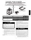
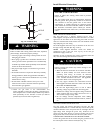
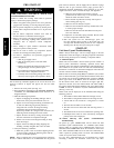
OUT
TEE
NIPPLE
CAP
IN
C99020
Fig. 10 -- Sediment Trap
FIRE OR EXPLOSION HAZARD
Failure to follow this warning could result in fire, explosion,
personal injury, death and/or property damage.
S Connect gas pipe to unit using a backup wrench to avoid
damaging gas controls.
S Never purge a gas line into a combustion chamber. Never
test for gas leaks with an open flame. Use a commercially
availabl e s oap solution made specifically for the detection
of leaks t o check all c onnections.
S Use proper length of pipe to avoid stress on gas control
manifold.
S If a flexible connector is required or allowed by authority
having jurisdiction, black iron pipe shall be installed at
furnace gas valve and extend a minimum of 2 in. (51 mm)
outside furnace casing.
S If codes allow a flexible connector, always use a new
connector. Do not use a connector which has previously
serviced anothe r gas appliance.
!
WARNING
8. Check for gas leaks at the field--installed and
factory--installed gas lines after all piping connections have
been completed. Use a com mercially available soap solution
made specifically for the detection of leaks (or method
specified by local codes and/or regulations).
Ins tall Electrical Connections
ELECTRICAL SHOCK HAZARD
Failure to follow this warning could result in personal
injury or death.
The unit cabinet must have an uninterrupted, unbroken
electrical ground. This ground may consist of an electrical
wire connected to the unit ground screw in the control
compartment, or conduit approved for electrical ground
when installed in accordance with NEC, NFPA 70 National
Fire Protection Association ( latest edition) (in Canada,
Canadian Electrical Code CSA C22.1) and local electrical
codes.
!
WARNING
HIGH--VOLTAGE CONNECTIONS
The unit must have a separate electrical service with a
field--supplied, waterproof disconnect switch mounted at, or within
sight from, the unit. Refer to the unit rating plate, NEC and local
code s for maximum fuse/circuit breaker size and minimum circuit
amps (ampacity) for wire sizing.
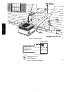
The field --supplied disconnect may be mounted on the unit over
the high--voltage inlet hole (See Fig. 5 and 6).
NOTE: Field supplied disconnect switch box should be
positioned so that it does not cover up any of the unit gas
combustion supply air louvers.
Operation of unit on improper line voltage constitutes abuse and
may cause unit damage that could affect warrant y.
UNIT COMPONENT DAMAGE HAZARD
Failure to follow this caution may result in damage to the
unit being installed.
1. Make all electrical connections in accordance with NEC
NFPA 70 (latest edition) and local electrical codes
governing such wiring. In Canada, all electrical
connections must be in accordance with CSA standard
C22.1 Canadian Electrical Code Part 1 and applicable
local codes. Refer to un it wiring diagram.
2. Use only copper conductor for connections between
field--supplied electrical disconnect switch and unit. DO
NOT USE ALUMINUM WIRE.
3. Be sure that high --voltage power to unit is within
operating voltage range indicated on unit rating plate.
4. Insulate low--voltage wires for highest voltage contained
within conduit when low--voltage control wires are in
same conduit as high--voltage wires.
5. Do not damage internal components when drilling
through any panel to mount electrical hardware, conduit,
etc.
!
CAUTION
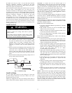
ROUTING POWER LEADS INTO UNIT
Use only copper wire between disconnect and unit. The high
voltage leads should be in a conduit until they enter the duct panel;
conduit termination at the duct panel must be watertight. Run the
high--voltage leads through the power entry knockout on the
power entry side panel. See Fig. 5 and 6 for location and size. For
single--phase units, connect leads to the black and yellow wires.
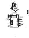
CONNECTING GROUND LEAD TO GROUND SCREW
Connect the ground lead to the chassis using the ground screw on
the control plate near the inducer switch (See Fig. 12).
577D-- -- A