


28
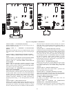
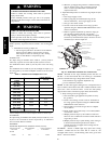
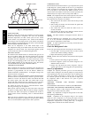
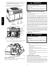
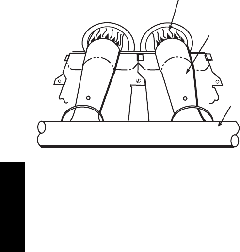
MANIFOLD
BURNER
BURNER FLAME
C99021
Fig. 21 -- Monoport Burner
LIMIT SWITCHES
Normally closed limit switch (LS) c ompletes the control circuit.
Should the leaving--air temperature rise above the maximum
allowable temperature, the limit switch opens and the control
circuit “breaks.” Any interruption in the control circuit instantly
closes the gas valve and stops gas flow to the burners. The blower
motor continues to run until LS resets. The furnace board STATUS
LED will display STATU S CO DE 33.
When the air temperature at the limit switch drops to the
low--temperature setting of the limit switch , the switch closes and
completes the control c ircuit. The direct--spark ignition system
cycles and the unit returns to normal heating operation.
ROLLOUT SWITCH
The func tion of the rollout switch is to close the main gas valve in
the event of flame rollout. The switch is located above the main
bur ners. When the temperature at the rollout switch reaches the
maximum allowable temperature, the control circuit trips, closing
the gas valve and stopping gas flow to the burners. The indoor fan
motor (IFM) continues to run until switch is reset. The furnace
board STATUS LED will display STATUS CODE 33.
CONTINUOUS FAN MODE
When continuous fan operation is requested by the UI indoor fan
motor will operate at continuous blower airflow. Continuous fan
operation is programmable. See the UI Owner’s Manual for
detailed instructions. Terminal EAC --1 is energized as long as the
indoor fan motor is energized.
During a call for gas heat, t he Evolution control will transition the
indoor fan motor to continuous blower airflow or gas heat airflow,
whichever is lowest. The indoor fan motor will remain ON until
the burners ignite, then shut OFF and remain OFF for the
blower-- ON delay allowing the heat exchangers to heat up more
quickly, then restarts at the end of the blower--ON delay period.
The indoor fan motor will revert to continuous--blower airflow
after the gas heating cycle is completed.
When the UI “calls for cooling”, the indoor fan motor will switch
to operate at cooling airflow. When the call for cooling is satisfied,
the indoor fan motor will operate an additional 90 seconds at
cooling airflow before transitioning back to continuous--blower
airflow.
When the call for continuous fan is removed, the indoor blower
will continue operating for an additional 5 seconds before shutting
down, if no other function requires blower motor operation.
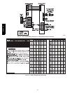
COMPONENT TEST
The Evolution Furnace Board features a gas component test system
to help diagnose a system problem in the case of a gas component
failure. To initiate the com ponent test procedure, ensure that there
are no UI inputs to the control (the ABCD connector can be
removed from the Evolution control board for this operation) and
all time delays have expired. Turn on setup switch SW1--6.
NOTE: The component test feature will not operate if the control
is receivi ng any UI signals or until all time delays have e xpired.
The component test sequence is as follows:
1. The control turns the inducer motor ON and keeps it ON
through step 3.
2. After waiting 10 seconds, the control turns the igniter ON
for 15 seconds, then OFF.
3. The control then turns the indoor fan motor on for 15
seconds, then OFF.
4. After shuttin g the bl ower motor OFF, the control runs the
inducer for 10 seconds, then turns it OFF.
NOTE: The EAC terminals are energized when the blower is
operating.
After the component test is completed, one or more status codes
(11, 25, or 41) will flash. See component test section or Status
Code Label for explanation of status codes.
NOTE: To repeat component test, turn setup switch SW1--6 to
OFF and then back ON.
Check for Refri gerant Leaks
Locate and repair refrigerant leaks and charge the unit as follows:
1. Use both high-- and low--pressure ports to relieve system
pressure and reclaim r emaining refrigerant.
2. Repair leak following accepted practices.
NOTE: Install a filter drier whenever the system has been opened
for repair.
3. Check system for leaks using an approved method.
4. Evacuate refrigerant system and reclaim refrigerant if no
additional leaks are found.
5. Charge unit with Puron (R--410A) refrigerant, using an
accurate scale. Refer to unit rating plate for required c har ge.
Start--Up Adjustments
Complete the required procedures given in the Pre-- Start-- Up
section before starting the unit. Do not jum per any safety devices
when operating the unit. Do not operate the unit in cooling mode
when the outdoor temperature is below 40°F(4°C) (unless
low--ambient operation is enabled in the UI). Do not rapid cycle
the compressor. Allo w 5 m in. between “on” cycles to prevent
compressor damage.
CHECKING COOLING AND HEATING CONTROL
OPERATION
See UI Installation Instructions for detailed system CHECKOUT.
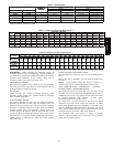
CHECKING AND ADJUSTING REFRIGERANT CHARGE
The refrigerant system is fully charged with Puron (R--410A)
refrigerant and is tested and factory sealed.
NOTE: Any adjustment to refrigerant charge must be done with
unit operating in HIGH stage.
NOTE: Adjustment of the refrigerant charge is not required
unless the unit is suspected of not having the proper R--410A
charge. The charging label and the tables shown refer to system
temperatures and pressures in cooling mode only. A refrigerant
charging label is attached to the outside of the unit.
577D-- -- A