


27
a. 129 sec. to complete one revolution
b. 3600/129 = 27.9
c.27.9x2=55.8ft
3
of gas flow/hr.
d. 55.8 x 1050 = 58,590 Btuh input.
In this example, the nominal input rate for low stage is 58,500
Btu/hr, so the low s tage manifold pressure is correctly set.
If the measured low stage rate is too low, inc rease the manifo ld
pressure to increase rate. If the measured low stage rate is too high,
decrease the manifold pressure to decrease rate.
NOTE: Double-- check that UI is running on low stage gas heat
while clocking the low stage firing rate.
4. Verify proper low stage gas heat temperatur e rise.
a. Furnace must operate within rise range listed on rating
plate.
b. Select ”COMFORT” or ”EFFICIENCY” mode on UI.
”COMFORT” mode will provide a warmer supply air
temperature, while ”EFFI CIENCY” will provide lower
gas consumption.
c. Make sure access panel is re--installed on t he unit.
d. Measure supply and return temperatures as close to the
unit as possible. Subtract the return temperature from
the supply temperature to determine rise. Rise should
fall within the range specified on the r ating plate.
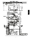
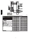
5. Adjust manifold pressure to obtain high stage input rate
(See Fig. 19).
a. Set unit to run for 20 minutes in high--stage gas heat
operation using the ”INSTALLER CHECKOUT” menu
on the UI.
b. Remove regulator adjustment cap from high stage gas
valve pressure regulator (See Fig. 19) and turn
high--stag e adjusting screw (3/16 or s maller flat--tipped
screwdriver) counterclockwise (out) to decrease rate and
clockwise (in) to increase input rate.
NOTE: DO NOT set high stage manifold pressure less than 3.2
IN. W.C. or more than 3.8 IN. W.C. for natural gas. If manifold
pressure is outside this range, change main burner orifices.
c. Re--install high stage regulator adjustment cap.
d. Leave manometer connected.
6. Verify natural gas high stage input rate.
a. Turn off all other gas appliances and pilots served by
the gas meter.
b. If unit is not running, set unit to run for 20 minutes in
high stage gas heat operation using the ”INSTALLER
CHECKOUT” menu on the UI.
c. Record number of seconds for gas meter to complete 1
revolution.
d. Divide number of seconds in step c. into 3600 (number
of seconds in 1 hour).
e. Multiply result of step d. by the number of cubic feet
shown for one revolution of test dial to obtain cubic feet
of gas flow per hour.
f. Multiply result of step f. by Btu heating value of the gas
to obtain total measured input shown in Table 6.
(Consult the local gas supplier if the heating value of
gas is not known).
EXAMPLE: Assume a 90,000 high stage input unit is being
installed. Assume that the size of the dial is 2 cubic ft., one
revolution takes 84 sec., and the heating value of the gas is 1025
Btu/ ft3. Proceed as follows:
a. 84 sec. to complete one revolution
b. 3600/84 = 42.9
c.42.9x2=85.8ft3ofgasflow/hr.
d. 85.8 x 1050 = 90,090 Btuh input.
In this example, the nominal input rate for high stage is 90,000
Btu/hr, so the high stage manifold pressure is correctly set.
If the measur ed high stage rate is too low, increase the manifold
pressure to increase r ate. If the measured high stage rate is too
high, decrease the manifold pressure to decrease rate.
NOTE: Double--check that User Interface is running on high stage
gas heat while clocki ng the low stage f iring rate.
7. Verify proper high stage gas heat temperature rise.
a. Furnace must operate within rise range listed on rating
plate.
b. Make sure access panel is re--installed on the unit.
c. Measure supply and return temperatures as close to the
unit as possible. Subtract the return temperature from
the supply temperature to determine rise. Rise should
fall within the range specified on the r ating plate.
NOTE: If the temp erature rise is out side the rating plate range ,
first check:
a. Gas input for low and high stage gas heat operation.
b. Derate for altitude, if applicable.
c. Return and supply ducts for excessive restrictions
causing static pressures in excess of . 5 IN. W.C.
d. Make sure model plug is installed.
8. Final Check
a. Turn off gas to unit
b. Remove manometer from pressure tap.
c. Replace pipe plug on manifold (See Fig. 20).
d. Turn on gas to unit.
e. Check for leaks.
CHECK GAS INPUT (PROPANE GAS)
Refer to propane kit installation instructions for properly checking
gas input.
NOTE: For installations below 2,000 ft (610 m), refer to the unit
rating plate for proper propane conversion kit. For installations
above 2,000 ft (610 m), contact your distributor for proper propane
conversion kit.
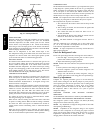
CHECK BURNER FLAME
With control access panel removed (See Fig. 24), observe the unit
heating operation. Watch the burner flames to see if they are light
blue and s oft in appearance, and th at the flames are approximately
the same for each burner. Pr opane will have blue flame (See Fig.
21) . Refer to the Maintenance section for information on burner
removal.
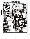
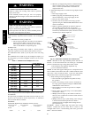
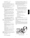
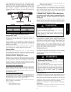
Pipe Plug
Manifold
A09082
Fig. 20 -- Burner Assembly
577D-- -- A