


23
open or shor ted at any time after initial validation, Status Code 53
will be displayed at amber STATUS LED.
Check for faults in wiring connecting sensor to OAT terminals.
Using an Ohm meter, check resistance of thermistor for a short or
open condition.
If thermistor is shorted or open, replace it to return the system to
normal operation. If fault is in the wiring connections, correcting
the fault will clear the code and return t he system to normal
operation.
NOT E: If fault condition is an open thermistor or a wiring problem
that appears to be an open thermistor and the power to the unit is
cycled off, the fault code will be cleared on the next power--u p but
the fault will remain and system operation will not be as expected.
This is becaus e on power--up, the unit control cannot discern
the difference between an open sensor or if a sensor is not
installed.
Sequence of Operation
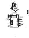
The 577D ----A packaged unit is designed for installation with a
communicating UI. This unit will not respond to commands
provided by a common thermostat except under certain emergency
situations described in Step 1—Start--Up and Troubleshooting.
The UI uses tempe rature, hum idity and other data supplied from
indoor and outdoor system components to control heating or
cooling system for optimum comfort. The unit will be commanded
by UI to supply airflow. The unit will operate the indoor blower at
requested airflow for most modes.
INDOOR AIRFLOW ADJUSTMENTS
The nominal requested airflow for air conditioner operations will
be 350 cfm per ton of nominal cooling capacity as defined by unit
size. Actual airflow request will be adjusted from nominal using
indoor and outdoor temperature and indoor humidity data to
optimize the system operation for occupant comfort and system
efficiency . Refer to UI literature for further system control details.
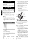
UNIT OPERATION HAZARD
Failure to follow this caution may result in unit dam age.
For cooling operation, the recommended airflow is 350 to
450 cfm for each 12,000 Btu h of rated c ooling capacity. For
heating operation, the airflow must produce a temperature
rise that falls within the range stamped on the unit rating
plate.
CAUTION
!
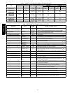
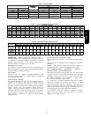
For gas heat operations, Table 3 shows the temperature rise in each
gas heatin g mode . Refer to these tables to determ ine the desired
heating airflow for t he system being installed.
NOTE: Be sure that all supply--and return--air grilles are ope n,
free from obstructions, and adjusted properly. Airflow can be
changed using the UI. See UI installation instructions for more
detail.
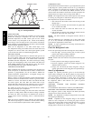
NOTE: Once the compressor has started and then has stopped, it
should not be started again until 4 minutes have elapsed. The
cooling cycle remains “on” until the room temperature drops to
point that is slightly below the cooling control s etting of the UI.
AIR CONDITIONER SEQUENCE OF OPERATION
COOLING OPERATION
With a call for first stage cooling, the outdoor fan, and low stage
compressor are energized. If low--stage cannot satisfy cooling
demand, high--stage cooling is energized by the UI. After second
stage is satisfied, the unit returns to low--stage operation until first
stage is satisfied or until second stage is required again. When both
first stage and second stage cooling are satisfied, the com pressor
will shut off.
NOTE: When two --stage unit is operating at low--stage, system
vapor (suction) pressure will be higher than a standard single--stage
system or high--stage operation.
NOTE: Outdoor fan motor will continue to operate for one
minute after compressor shuts off, when outdoor ambient is greater
than or equal to 100°F(38°C).
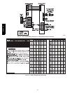
UTILITY INTERFACE WITH Evolution CONTROL
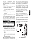
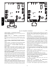
The utility curtailment r elay s hould be connected to factory
supplied pig tails (PINK, connected to R, VIOLE T connected to Y2
on the control board) located in the low voltage splice box (See
Fig. 16, 18 and 18). This input allows a power utility device to
interrupt compressor operation during peak load periods. When the
utility sends a signal to shut the system down, the UI will display
“Curtailment Active”.
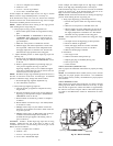
COMPRESSOR OPERATION
When the compressor is operating in low stage, the modulating
ring is deactivated, allowing two internal bypass ports to close off
33% of the scroll compression area so the system operates at part
load capacity. The 24--volt solenoid coil is de--energized in
low--stage operation.
When the compressor is operating at high stage, the modulating
ring is activated, sealing the bypass ports, which allows the
compressor to operate at full load capacity. The 24--volt solenoid
coil is energized in high stage operation.
CRANKCASE HEATER OPERATION (IF APPLICABLE)
The crankcase heater is energized during off cycle below 65_F
(18_C) outdoor air temperature.
OUTDOOR FAN MOTOR OPERATION
The outdoor unit control energizes the outdoor fan any time the
compressor is operating. The outdoor fan remains energized if a
pressure switch or compressor overload should open. Outdoor fan
motor will continue to operate for one minute after the compressor
shuts off when the outdoor ambient is greater than or equal to
100_F(38°C).
TIME DELAYS--AIR CONDITIONER OPERATIONS
The unit time delays include:
S Five minute time delay to start cooling operation when there is a
call from t he thermostat or user interface. To bypass this feature,
momentarily short and release Forced Defrost pins.
S Five minute compressor recycle delay on return from a
brown--out condition.
S Two minute time delay to return to standby operation from last
valid communication (with Evolution only).
S One minute time delay of outdoor fan at termination of cooling
mode when outdoor ambient is greater than or equal to 100_F
(38°C).
S There is no time delay between air conditioner staging from low
to high and from high to low capacity; t he com pressor will change
from low to high and from high to low capacity as demand
dictates.
577D-- -- A