


40
BAS-311E.311EL.326E.326EL
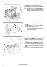
Chapter 3. Assembly
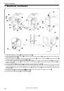
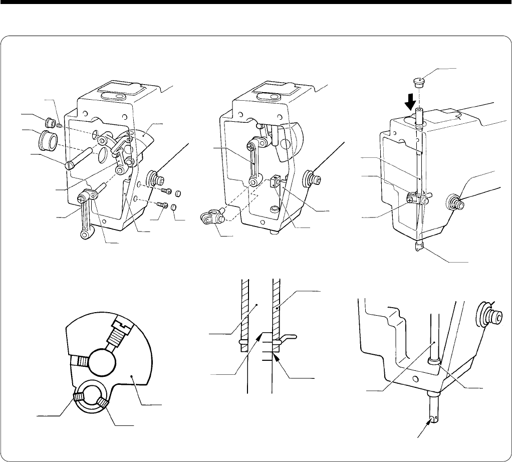
7. Needle bar mechanism
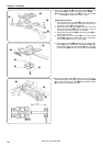
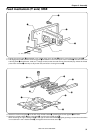
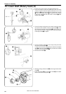
1. Temporarily tighten the screw w of the needle bar guide q.
2. Pass the thread take-up support stud e through the thread take-up assembly r, lightly press the former, and secure
them using the set screw t.
3. Pass the needle bar crank y through the thread take-up assembly r and the counter crank u, adjust the set screw i
to the screw flat, and tighten the set screws i and o.
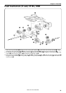
4. Fit the chamfering side of the needle bar guide slide block !0 into the groove on the needle bar guide q, and insert the
shafts of the needle bar clamp !1 into the needle bar connecting rod !2 and the needle bar guide slide block !0, as
shown in the figure.
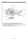
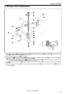
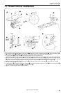
5. Insert the needle bar !3 from the top of the machine into the needle bar clamp !1.
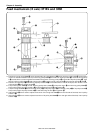
6. Turn the pulley to set the needle bar !3 at its lowest position. Move the needle bar vertically so as to align the second
lowest reference line A (for using needle DP ✕ 17) or the highest reference line a (for using needle DP ✕ 5) on the
needle bar !3 with the lower end of needle bar bush (D) !4. Tighten the screw !5 with the cut section of the needle bar
facing the front.
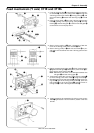
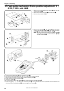
7. Find the position of the needle bar guide q so that the pulley rotates easily, and tighten the screw w.
8. Attach the oil cap !6 and the rubber caps !7, !8, and !9.
9. Fit the needle bar thread guide @0 on the needle bar !3.
q
t
!0
!5
u
!1
!2
!3
!1
!6
w
u
q
!7
e
y
!9
!8
o
i
!4
!3
aDP×5
!4
!3
r
!2
ADP×17
Cut section
@0