


107
BAS-311E.311EL.326E.326EL
Chapter 7
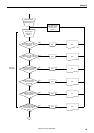
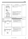
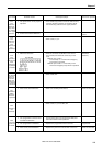
#4
The work
clamp does
not move
up and
down
when the
foot switch
is stepped
on.
Probable causes
4. Power PCB defective.
5. The air valve is defective.
6. The control circuit board (#3) is
defective.
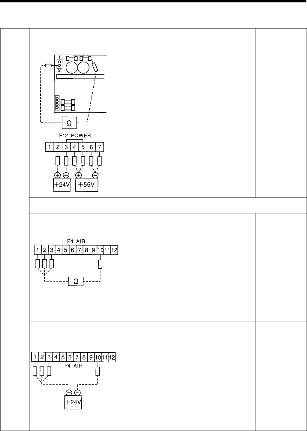
Check/repair/adjust
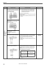
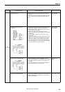
• Measure the resistance between a terminal in the
center of the power PCB and pin 2 in connector P5
(DC300).
The resistance should be ∞Ω.
• Remove connector P12 (POWER) on the control
circuit board, turn on the power, and measure the
voltage across pins 4 and 6, pins 5 and 6, pins 5
and 7 on the cord.
The voltage in each case should be +55V.
Measure the voltage across pins 2 and 3. The
voltage should be +20V to 24V.
After measurement, turn off the power, wait at
least 5 minutes, and insert P12.
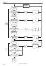
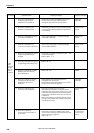
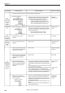
• Pull out connector P4 (AIR) on the control circuit
board and measure the resistance between the
following pins in the connector on the cord:
Pins 1 and 10 (air valve for right work clamp)
Pins 2 and 10 (air valve for left work clamp)
Pins 3 and 10 (air valve for presser foot; only
for optional specification)
The resistance in each case should be 300 - 400 Ω.
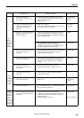
• Pull out connector P4 (AIR) and measure the
voltage across the following pins in the connector
on the PCB:
Pins 1 and 10 (air valve for right work clamp)
Pins 2 and 10 (air valve for left work clamp)
Pins 3 and 10 (air valve for presser foot; only
for optional specification)
The voltage in each case should be +20V to 24V.
After measurement, turn off the power, wait at
least 5 minutes, and insert P4.
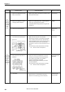
Parts to be replaced
Power PCB
Air valve
Valve harness assy.
Control circuit
board.
Error status
Work clamp for pneumatic specification (BAS-311E and 325E)